In power systems, transformers are fundamental for voltage conversion and energy transfer. A critical question arises: Does a transformer's output voltage under full load equal its rated voltage? The definitive answer is no, and this article explains the underlying principles, supported by engineering standards and quantitative analysis.
1. Definition of Rated Voltage
Rated Voltage (IEEE/IEC Standard):
The rated voltage of a transformer is defined as its no-load output voltage (i.e., secondary voltage when the secondary winding is open-circuited). For example, a transformer labeled "400V" delivers exactly 400V at no load.
Full-Load Voltage:
Under full-load conditions, the actual output voltage deviates downward due to inherent losses. This is quantified by Voltage Regulation (VR).
2. Why Voltage Drops Under Full Load
Key Factor: Transformer Impedance
Every transformer has internal impedance (ZZ), comprising:
Resistance (RR): Copper losses in windings.
Leakage Reactance (XX): Magnetic flux leakage.
This impedance causes a voltage drop proportional to the load current:
ΔV=Iload×(Rcosϕ+Xsinϕ)ΔV=Iload×(Rcosϕ+Xsinϕ)
where cosϕcosϕ is the load power factor.
Voltage Regulation Formula
VR%=VR%=
Typical VR Values:
Distribution Transformers: 2–5%
Power Transformers: 5–10%
3. Practical Example
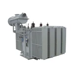
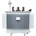
Consider a 1600 kVA oil-cooled transformer with:
Rated No-Load Voltage: 400 V
Impedance (ZpuZpu): 4%
Load Power Factor: 0.8 lagging
Calculation:
Vfull-load=Vno-load−(Vno-load×Zpu×cosϕ)=400−(400×0.04×0.8)=400−12.8=387.2 VVfull-load=Vno-load−(Vno-load×Zpu×cosϕ)=400−(400×0.04×0.8)=400−12.8=387.2 V
Voltage Regulation:
VR%=400−387.2387.2×100%≈3.3%VR%=387.2400−387.2×100%≈3.3%
Result: Output voltage drops to 387.2 V (–3.3%) under full load.
4. Mitigation Strategies
To maintain rated voltage under load:
a) Tap Changers
On-Load Tap Changer (OLTC):
Dynamically adjusts primary turns to compensate for voltage drop.
Example: A +5% tap raises secondary voltage by 5%.
Off-Circuit Taps:
Manual adjustment for fixed voltage correction.
b) Automatic Voltage Regulators (AVR)
Install external AVR systems (e.g., STATCOM) to inject reactive power and stabilize voltage.
c) Design Optimization
Lower impedance transformers (e.g., Zpu<4%Zpu<4%) reduce voltage drop but increase short-circuit currents.
5. Standards Compliance
IEEE C57.12.00:
"Rated voltage is the no-load voltage. Full-load voltage shall be calculated by subtracting the impedance drop."
IEC 60076-1:
"The output voltage under rated load is derived from the no-load voltage minus the voltage drop."
6. Real-World Implications
Grid Stability: Voltage drop affects sensitive loads (e.g., motors, industrial machinery). Utilities enforce ±5% voltage tolerance (ANSI C84.1).
Transformer Testing:
Routine tests measure ZpuZpu and VR% to validate design compliance.
Conclusion
A transformer cannot maintain its rated voltage under full load due to inevitable impedance-induced voltage drops. The deviation is quantified by Voltage Regulation, typically ranging 2–10% based on design and load profile. Mitigation requires tap changers, AVR systems, or low-impedance designs. Engineers must factor in VR% during system planning to ensure voltage stability within regulatory limits.