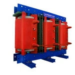
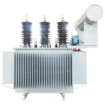
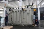
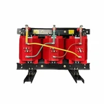
The transport and seismic capabilities of transformers are critical to ensure their mechanical integrity during shipment, installation, and operation in areas prone to earthquakes. The design criteria focus on both static and dynamic loads to prevent deformation, displacement, or damage. Here are the key considerations:
1. Transport Capability Criteria
Transport loads occur due to vibrations, shocks, and tilts during shipping by road, rail, sea, or air. Transformers must be designed to handle these stresses to avoid damage.
a) Static Load Criteria
Weight Distribution
Load distribution is calculated to ensure the transformer is stable during transport.
Support points, lifting lugs, and jacking pads must be positioned based on the transformer's center of gravity (CG).
Allowable Tilt Angles
Transformers are often designed to withstand a tilt of 10-15 degrees during transport.
Additional bracing may be required for components like bushings and radiators to prevent tilting stress.
Container or Frame Design
The transformer is mounted securely within transport frames to minimize movement. These frames are designed based on weight and force calculations.
b) Dynamic Load Criteria (Shock and Vibration)
Shock Loads
Transformers must withstand short-term shocks equivalent to 2-5g (acceleration due to gravity) during handling and braking.
Drop test simulations are performed to evaluate whether the transformer can absorb sudden impacts.
Vibration Testing
Transport vibration analysis ensures no damage to internal components like windings, insulation, or core laminations.
Frequencies between 1-100 Hz are typically simulated to match real-world transport vibrations.
Compliance Standards
ASTM D4169: For performance testing during distribution.
IEC 60068-2: Environmental testing for transport shocks and vibrations.
2. Seismic Capability Criteria
Seismic loads occur due to ground accelerations during an earthquake. Transformers must be designed to stay operational and prevent internal displacements or oil spills during seismic events.
a) Seismic Zone and Site Classification
Seismic Zones: Site-specific data (e.g., from the USGS seismic hazard map) is used to determine peak ground acceleration (PGA) values.
Soil Conditions: The stability of soil or foundation plays a role in seismic design, as soft soils amplify ground motion.
b) Seismic Forces and Stress Analysis
Seismic Load Calculation
The horizontal force FsF_sFs is calculated using the following formula:
Fs=W×AhF_s = W \times A_hFs=W×Ah
where WWW is the weight of the transformer and AhA_hAh is the horizontal acceleration (a percentage of gravity, g).
Natural Frequency
The transformer and its foundation should be designed to avoid resonance frequencies with seismic waves.
Typically, the structure's natural frequency is kept below 5 Hz.
Anchor Bolts and Foundation Design
Bolts are designed to resist uplift and shear forces from seismic activity.
Foundation pads may need reinforcement with base isolators or shock absorbers in high-risk areas.
c) Finite Element Analysis (FEA)
FEA simulations are conducted to evaluate stress and deformation under seismic loads.
Critical components like the windings, core, bushings, and radiators are analyzed for stress concentration.
d) Seismic Testing and Standards Compliance
IEEE 693: Provides guidelines for seismic qualification of electrical equipment.
Zones are classified as low, moderate, or high seismic risk with corresponding design requirements.
IBC (International Building Code): Defines seismic design categories for critical infrastructure.
ISO 8528: Used for seismic performance testing of power equipment.
3. Combined Transport and Seismic Considerations
Internal Bracing and Dampers
Components such as radiators and bushings are braced to avoid damage during both transport and seismic events.
Shock absorbers or elastomeric mounts may be used to absorb dynamic loads.
Oil Containment Systems
Transformers are designed to prevent oil leaks during seismic events by reinforcing gaskets and seals.
Safety Factor
A safety factor of 1.5 to 2.0 is usually applied to account for uncertainties in seismic load predictions and transport handling.
These criteria ensure that transformers can endure mechanical stress during transport and seismic loads without compromising structural integrity or operational reliability.


