

In July, a contractor in Phoenix called us about a 2,000 kVA dry type unit that had been tripping its winding temperature alarm at 60% load since the first hot week. The transformer tested clean. The room did not: a container-style electrical house with two 24-inch louvers, one of them sealed with foam against desert dust.
That call is the reason this article exists. Dry type transformer installation gets reviewed for clearances, cable bend radius and seismic anchors, and almost never reviewed for air. Then the doors close, the unit runs, and the only cooling medium it has, the room air, starts to heat up.

Here is the part most buyers miss: a dry type transformer does not come with a cooling system you can walk around and inspect. It comes with a room.
Why Dry Type Transformer Installation Fails in the Room, Not the Coil
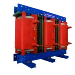
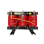
An oil immersed unit pushes its losses into oil, then into radiators, usually outdoors. A cast resin transformer has no radiator. The windings are encapsulated, the enclosure is ventilated, and every kilowatt of loss is dumped into the air moving past the core and coils. That air is the heat sink, and its temperature is the one variable in the rating that the factory cannot control.
IEEE C57.12.01 sets the basis: 40°C maximum ambient, and for a 150°C rise design on a 220°C insulation system, an average winding rise of 150 K at rated load. Read that as a contract, 40°C air in and 150 K rise allowed. Change the first number and the second one stops being true. In a 52°C room the winding runs roughly 12 K hotter at the same current, and the hottest spot moves toward the limit the insulation system was assessed against. The method for putting a number on that is the IEEE guide for hottest-spot temperature in dry-type units, and the test code behind every temperature-rise figure was revised in September 2026.
Both documents are worth keeping next to the submittal: the IEEE C57.12.91-2026 test code for dry-type transformers and the IEEE C57.134-2024 hottest-spot guide. Neither one will size your louvers for you, but they are the basis any reviewer will use when the room runs hot.
Step One: Read the Losses Off the Nameplate, Not the kVA
The number you need is not 2,000 kVA. It is the total loss in kilowatts at the load you actually expect, and it is already on the nameplate in two pieces. No-load loss is fixed the moment the core is energized. Load loss varies with the square of current, so at half load it is a quarter of the rated figure.
Take a typical 2,000 kVA unit: 3.1 kW no-load loss and 16.9 kW load loss at rated current. That is 20.0 kW of heat rejection at full load, or about 68,000 BTU/h, and it is the number the mechanical engineer needs.
| Load factor | Load loss (kW) | No-load loss (kW) | Heat to room (kW) | Heat to room (BTU/h) |
| 0% (energized, no load) | 0.0 | 3.1 | 3.1 | 10,600 |
| 50% | 4.2 | 3.1 | 7.3 | 24,900 |
| 75% | 9.5 | 3.1 | 12.6 | 43,000 |
| 100% | 16.9 | 3.1 | 20.0 | 68,200 |
Two corrections before anyone takes that table to a louver supplier. First, load loss is quoted at a reference temperature stated in the test report, commonly 75°C or 85°C; at real operating temperature the winding resistance is higher and the loss is too, so treat the nameplate figure as a floor. Second, the room does not only see the transformer. Medium-voltage switchgear, busway, VFD lineups and lighting all reject heat into the same volume, and in a lineup we usually add 5 to 15 kW for the neighbours before we hand a number to the HVAC contractor.
Step Two: Convert Kilowatts to CFM
The airflow calculation is one line of arithmetic. In imperial units, BTU/h equals 1.08 times CFM times the air temperature rise in °F, so CFM equals 3,160 times kW divided by the rise in °F. In metric, cubic metres per second equals kW divided by 1.206 times the rise in K. That is the whole of transformer room ventilation sizing, and it takes five minutes once you have the loss figure.
For the 20 kW unit, a 10°F (5.6 K) room rise needs about 6,320 CFM, a 15°F rise needs 4,210 CFM, and a 20°F rise needs 3,160 CFM. Which one you can use is decided by the design outdoor temperature, not by preference. If the air comes straight from outside, the rise you can afford is 40°C minus the design ambient. A Phoenix design day at 43°C leaves nothing: an outdoor-air-only room cannot hold the 40°C basis at all, which is why desert sites either add mechanical cooling or accept a documented derating. A site in Ohio with a 32°C design ambient has 8 K to work with and can stay on outdoor air alone.
| Room air rise | Airflow for 20 kW (CFM) | Free area at 500 fpm (sq ft) | Nominal louver area at 45% free (sq ft) |
| 10 °F (5.6 K) | 6,320 | 12.6 | ~28 |
| 15 °F (8.3 K) | 4,210 | 8.4 | ~19 |
| 20 °F (11.0 K) | 3,160 | 6.3 | ~14 |
Now the detail that sinks most rooms. A louver is sold by nominal size, but air only moves through its free area, typically 45 to 50% of nominal. Two 24 by 24 inch louvers give 8 sq ft nominal and about 3.6 sq ft free, which at 500 fpm passes 1,800 CFM. The Phoenix room in the opening paragraph needed 6,320 CFM and had roughly a third of the free area required. The transformer was never the problem.
The same logic applies to the relief path. Air that comes in has to leave, through an opening of at least the same free area, on the opposite side of the room, with both a high and a low path so the hot layer at the ceiling can escape. Door undercuts and cable penetrations are not a relief path, and a closed fire damper is not either.
The code position is deliberately unhelpful on this point. Section 450.9 of the NFPA 70 National Electrical Code requires ventilation adequate for the transformer's cooling, and stops there, with no CFM and no temperature rise. That is not an oversight: adequate depends on the losses, the design ambient and the room, which is exactly why the number has to come from the project rather than from the code book.
Fan Cooling Adds Capacity and Adds Heat
Many buyers pay for the fan-cooled rating because it looks like free capacity: the same core, 2,000 kVA base and 2,500 kVA with fans running. The room pays for it. Load loss scales with current squared, so at the fan rating the load loss goes from 16.9 kW to about 26.4 kW, and the fan motors add roughly 1.5 kW. Heat rejection climbs from 20 kW to about 31 kW, an increase of 55% in airflow for 25% more kVA. If ventilation was sized for the base rating, the day the fans start is the day the room overheats.
Harmonic load behaves the same way. Non-sinusoidal current raises winding eddy losses well beyond the 60 Hz value, and a K-rated or derated unit still rejects that extra heat into the same room. Where the transformer shares space with VFD lineups, the drives are frequently a larger heat source than the transformer at part load, and nobody includes them in the louver calculation.
What a Starved Room Does to the Winding
The symptoms arrive in a predictable order. Winding sensors read higher than the factory test curve at part load. The alarm stage on the winding relay starts to chatter in the afternoon and resets overnight. Then the unit trips on a day when the load has not changed, because the ambient did.
The damage is slower than the alarm. Insulation thermal ageing roughly doubles for every 6 to 8 K above the rated hot spot, so 12 K of extra room temperature is not a 12 K problem, it is a service-life problem. Cast resin adds one more failure mode: thermal cycling cracks the encapsulation, a crack becomes a partial discharge site, and partial discharge inside a cast winding does not heal on its own. The unit keeps running, tests progressively worse, and fails at a moment nobody chose.
On one dry type transformer installation we were called back to in Texas, three 1,500 kVA units shared a 12 by 6 metre room with a single square metre of louver. By the third summer the units were being held at roughly 80% of nameplate by their own winding protection. The fix was not a new transformer. It was 14 sq ft of additional free area and a relief damper, installed in two days.
What to Put in the Specification
If you are writing the spec, or reviewing a submittal, these six items settle the air side before the unit is built:
• Losses at the expected load, not just at nameplate: no-load and load loss from the quotation, with the reference temperature stated.
• Design ambient inside the room, taken from the local design dry-bulb, plus any solar gain through the roof.
• Whether the fan rating will be used, and if so, the higher loss figure that comes with it.
• Target room rise, typically 5 to 8 K, which sets the CFM.
• Louver free area, in square feet, not nominal size, with the relief path shown on the drawing.
• Winding temperature alarm and trip settings, written into the commissioning sheet so the first summer is not a surprise.
Transformer room ventilation sizing belongs on the electrical drawing set, next to the transformer schedule, not only on the mechanical set where the electrical contractor will never look for it. Our factory in Jiangsu runs 120,000 sq m of production space with more than 180 sets of major equipment and 37 patents, and every dry type quotation leaves with loss data per load point, because that is the input the room design needs. As an Eaton joint venture partner since 2023, we also sit inside North American submittal reviews often enough to know which question comes first.
It is rarely the impedance. When a US contractor sends us an RFQ for a cast resin transformer, our engineers have learned to ask for the room drawing before they ask for the tap range, because a 2,000 kVA unit in an undersized room is a 1,600 kVA unit with a warranty claim attached.
Order the Air With the Unit
Dry type transformer installation is a two-discipline job that is usually let as one contract and reviewed as none. The electrical package assumes the room is ventilated, the mechanical package assumes the transformer is air-cooled and therefore somebody else's problem, and the owner finds out in July.
The fix costs almost nothing at design stage and a great deal afterwards. Send the room dimensions and the design ambient with your next enquiry through ryan-transformers.com, and we will return the loss table, the airflow figure and the louver area with the quotation, so the mechanical contractor is sizing against real numbers instead of a nameplate.
About the Author
This article was written by the engineering team at Ryan Electric, a transformer manufacturer in Jiangsu, China, building UL, cULus, CSA and IEC certified dry type and oil immersed transformers for utilities, data centres and industrial projects across North America, the Middle East, Southeast Asia and Africa.