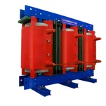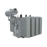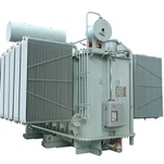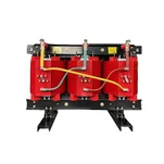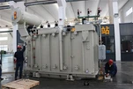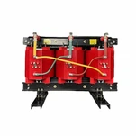


Connecting a utility-scale photovoltaic plant to the medium-voltage grid requires far more than stepping up 600 V or 800 V inverter outputs to 34.5 kV. Solar inverters generate high-frequency pulse-width modulation (PWM) harmonics, inject direct-current (DC) bias into transformer windings, and subject magnetic cores to severe cyclic thermal stress during peak daily irradiance. Specifying a rugged solar farm step-up transformer requires electrical engineers and EPC contractors to evaluate multi-winding configurations, harmonic eddy losses, electrostatic shielding, and thermal aging dynamics before releasing submittal drawings.
The Engineering Challenges of Modern Solar Inverter Interconnection
Unlike conventional distribution networks where load currents remain predominantly sinusoidal, central and string solar inverters produce non-sinusoidal output waveforms rich in high-frequency harmonics. Modern grid-tied inverters utilize insulated-gate bipolar transistor (IGBT) bridges switching between 2 kHz and 10 kHz. While output low-pass filters attenuate much of the switching carrier frequency, substantial harmonic currents (spanning the 5th, 7th, 11th, and 13th orders up to the 49th order) penetrate the low-voltage transformer windings.
These harmonic currents do not merely increase basic copper I²R ohmic losses. High-frequency components create non-uniform current distribution across the conductor cross-section through skin and proximity effects. In accordance with IEEE C57.110, winding eddy current losses (P_EC) increase proportionally with the square of the harmonic frequency (h²), while other stray load losses (P_OSL) in core clamping plates, tie rods, and structural tank steel escalate rapidly. If unmitigated, these localized losses generate intense hot-spots that accelerate cellulose insulation degradation.
Furthermore, asymmetric inverter switching or grid faults can introduce small direct-current components into the transformer secondary windings. Even a DC offset as small as 0.1% to 0.5% of rated current can shift the magnetic operating point on the B-H magnetization curve of grain-oriented silicon steel cores. This DC pre-magnetization pushes the core into half-cycle saturation, triggering asymmetrical magnetizing inrush currents, increasing no-load losses by up to 20%, elevating acoustic noise by 8 to 12 dB(A), and generating stray magnetic flux that overheats structural tank components.
Split-Secondary vs. Dual-Winding: Selecting the Right Transformer Architecture
In modern multi-megawatt PV blocks (typically 2.5 MVA to 4.16 MVA per skid), project developers must choose between utilizing separate two-winding transformers or integrating a single three-winding split-secondary transformer. A split-secondary design features two electrically isolated low-voltage (LV) windings (LV1 and LV2) coupled to a common high-voltage (HV) winding on the same magnetic core limb.
When evaluating a solar inverter transformer, the split-secondary topology offers substantial balance-of-plant (BOP) cost and footprint savings by allowing two separate central inverters to connect to a single step-up unit without circulating circulating cross-currents. However, maintaining strict impedance symmetry is essential: the impedance between HV-LV1 and HV-LV2 must match within a tight 2.0% tolerance to guarantee equal load sharing across both inverter stages.
Another vital parameter is the cross-impedance between LV1 and LV2 (Z_LV1-LV2). Specifying a high cross-impedance-typically greater than 12% to 15%-effectively decouples the two inverter circuits. This decoupling prevents harmonic resonance between inverters and limits fault current contribution from one healthy inverter stage into an adjacent faulted low-voltage branch.
Below is a technical comparison of standard two-winding configurations versus split-secondary three-winding architectures for utility solar PV generation skids:
| Design Parameter | Standard Two-Winding Unit | Split-Secondary Three-Winding Unit |
|---|---|---|
| Inverter Integration | Connects to single central inverter | Connects two independent inverters (e.g., 2x 1.5 MW) |
| Balance of Plant (BOP) Cost | Higher (requires dual transformers & pads) | Lower (consolidates footprint, foundation, and cabling) |
| LV-to-LV Cross Coupling | N/A (separate units) | High cross-impedance (>12%) prevents inverter interaction |
| Harmonic Thermal Stress | Distributed across dedicated tanks | Requires decoupled cooling ducts and electrostatic shielding |
| Impedance Balance Requirement | Standard ±7.5% factory tolerance | Strict HV-LV1 vs HV-LV2 symmetry within ±2.0% |
| Short-Circuit Level on Inverter | Higher fault current contribution | Split impedance limits fault current at inverter AC terminals |
Mitigating Inverter Harmonics with K-Factor and Electrostatic Shielding
To prevent premature insulation breakdown, an engineered solar farm step-up transformer must incorporate specific design measures tailored for harmonic loads. Calculating the appropriate K-factor rating (typically K-4 to K-9 for central inverters) ensures that the magnetic core and winding conductors withstand additional stray eddy heating in accordance with IEEE C57.12.00 standard requirements. A K-4 rating signifies that the transformer can handle four times the eddy current losses of a standard linear sinusoidal transformer without exceeding rated temperature rise limits.
A critical hardware defense against high-frequency inverter noise is the integration of an electrostatic shield. Placing a continuous 0.1 mm grounded copper shield between the high-voltage and low-voltage windings provides effective capacitive decoupling. This shield diverts high-frequency common-mode PWM voltage spikes (dV/dt rates often exceeding 1000 V/µs) directly to station ground before they can stress the inter-turn insulation of the medium-voltage grid windings.
When we test solar farm step-up transformers in our test bay, the first thing our engineers check under simulated inverter non-sinusoidal loading is winding hot-spot temperature rise and harmonic eddy current loss distribution across the split low-voltage coils. Verifying that winding hot-spots stay well within design thresholds under 120% cyclic peak solar irradiance prevents thermal aging over 25-to-30-year project lifecycles.
Efficiency Compliance and Dielectric Fluid Selection
In North American jurisdictions, utility-scale liquid-immersed transformers must satisfy strict efficiency mandates under DOE 10 CFR Part 431 efficiency regulations. Achieving compliant no-load and full-load losses while handling high harmonic currents requires laser-treated high-permeability grain-oriented silicon steel cores with step-lap mitered joints and optimized flux densities operating below 1.65 Tesla.
Dielectric fluid selection plays an equally vital role in solar installations. While standard mineral oil provides dependable dielectric insulation, high-temperature natural ester fluids (such as FR3) offer a fire point above 300°C and superior environmental safety for ground-mounted solar fields near agricultural lands or sensitive water tables. Natural ester fluids also absorb moisture released by cellulose insulation, preserving paper tensile strength and extending service life under extreme ambient temperatures.
Because solar transformers operate under cyclic loading-ramping from zero at sunrise to full capacity at solar noon and enduring high ambient heat-specifying a 65°C average winding rise / 80°C hot-spot rise paired with high-temperature thermally upgraded Kraft paper (TUK) provides robust thermal headroom against premature insulation aging.
Ryan Electric: Precision Manufacturing for Utility-Scale Solar Projects
As an experienced pad mounted transformer manufacturer and an official Eaton joint venture partner since 2023, Ryan Electric manufactures utility-scale solar transformers across our 120,000 m² state-of-the-art production base. Equipped with advanced automated foil winding machines, vacuum drying chambers, and comprehensive testing laboratories, we deliver customized step-up solutions certified to UL, CSA, IEEE, DEKRA, and CE standards.
Whether your project demands a 2500 kVA pad-mounted skid or a 5000 kVA three phase transformer custom engineered with dual 800 V low-voltage windings, electrostatic copper shielding, and integrated FR3 natural ester fluid, our engineering team optimizes core geometries and impedance profiles to maximize solar farm annual energy yield (AEY).
Key Specification Checklist for Solar Transformer Procurement
Before finalizing your equipment schedule, ensure your technical procurement specifications address the following essential parameters:
1. Rated Power & Voltage Profile: Specify base kVA rating (e.g., 2500 kVA / 34.5 kV GrdY to 2x 800 V Delta/Wye) with maximum solar inverter AC terminal voltage variations (±10%).
2. Harmonic Spectrum & K-Factor: Define total harmonic distortion (THD < 5%) and required K-factor rating (K-4 minimum) based on inverter manufacturer data sheets.
3. DC Bias Withstand: Mandate continuous DC component withstand capability of at least 0.5% rated current without core saturation or audible noise spikes.
4. Electrostatic Shielding: Require grounded copper Faraday shielding between HV and LV coils for high-frequency PWM surge protection.
5. Enclosure & Security: For pad-mounted installations, verify tamper-resistant cabinet construction meeting IEEE C57.12.28 enclosure integrity requirements.
Investing in a properly engineered solar farm step-up transformer protects multimillion-dollar inverter assets, eliminates unexpected thermal curtailments, and guarantees dependable grid compliance throughout the lifespan of your renewable energy asset.
About the Author
David Chen is a Principal High-Voltage Systems Engineer at Ryan Electric with over 16 years of experience in medium-voltage power distribution and renewable energy interconnection. Specializing in IEEE/UL/CSA certified liquid-filled and dry-type transformer engineering, he has overseen the design and commissioning of over 3.5 GW of solar, BESS, and data center step-up systems globally.