

A colocation developer in Virginia asked us a short question last month: if the racks run on 800 VDC now, do we still need to buy transformers? The question is fair, because most of the 800 VDC material published since 2025 reads as if the low-voltage AC stage disappears. It does not - not in 2026, and not in the buildings pouring concrete this quarter. What changes is the duty the 800 VDC data center transformer sees: a rougher harmonic spectrum, tighter impedance matching, and a load profile that steps instead of drifts.
Here is the engineering picture we hand to EPC teams when this comes up, and the four specification items that separate a unit that lasts twenty-five years from one that runs hot from its first summer.
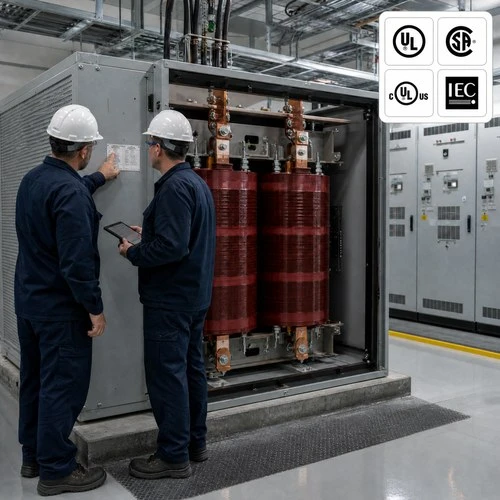
What an 800 VDC Data Center Transformer Actually Sees
Every 800 VDC design still begins with a medium-voltage AC service. The utility brings in 13.8 kV or 34.5 kV, the 800 VDC data center transformer steps that down to the rectifier's AC input - usually 400 V to 690 V - and the rectifier produces the 800 VDC bus that feeds the racks. NVIDIA frames the transition around the same constraint we hear from every rack vendor: 54 V in-rack distribution was designed for kilowatt racks and does not scale to the 1 MW racks now being planned. See the NVIDIA 800 V HVDC technical note for their framing.
The arithmetic explains the urgency. One megawatt at 54 V is roughly 18,500 A. The same megawatt at 800 V is 1,250 A. Conductor mass, I²R loss and busbar temperature all follow current rather than power, so raising the DC bus voltage is mostly a copper and cooling decision. It is not a decision that removes the transformer - the AC side still has to be stepped down, isolated and protected before any rectifier can work.
Equipment vendors are moving on that timeline. Vertiv confirmed an 800 VDC power portfolio for the second half of 2026, positioned ahead of the Kyber and Rubin Ultra rack rollouts (Vertiv announcement). Delta's May 2026 release pairs 18.5 kW AC/DC power shelves running near 98% efficiency with a solid-state transformer quoted at 98.5% for medium-voltage AC straight to 800 VDC (Delta 800 VDC release). Read those two numbers together and the sequence becomes clear: the rectifier moves into the row this year, the solid-state transformer arrives after it, and the conventional transformer carries the load in between.
Three Architectures, Three Different Transformers
Not every 800 VDC hall is wired the same way, and the 800 VDC data center transformer you need depends on which one you are building. These are the three we are quoting against in 2026.
| Architecture | Where the transformer sits | Status in 2026 | What changes in the spec |
|---|---|---|---|
| Central rectifier room | MV/LV transformer feeds a rectifier bank that produces the 800 VDC bus | Shipping on new hyperscale builds | Harmonic duty, K-factor rating, impedance matching across parallel units |
| In-row AC/DC shelves | Transformer delivers 415/480 V AC to row-level power shelves | Most colocation retrofits and enterprise AI halls | Lower harmonic content, but tighter voltage regulation and footprint limits |
| Solid-state transformer | MV AC converted directly to 800 VDC, no low-frequency transformer | Pilot units and first commercial releases; volume from 2027 | Isolation design, DC output control, and a new set of certification questions |
The mistake we see in RFQs is a specification written for the second row of that table and used to buy equipment for the first. A row-level power shelf draws a comparatively clean current. A thyristor or diode rectifier bank does not. Same kVA, same voltage ratio, very different winding stress.
The Four Specifications That Actually Change
Harmonic duty. A 6-pulse rectifier produces characteristic 5th, 7th, 11th and 13th harmonics; a 12-pulse arrangement cancels the 5th and 7th and leaves the rest. The transformer carries those currents as extra winding loss and local hot spots. Specify a K-factor rating (K-4, K-13, K-20 under UL 1561) and require derating to IEEE C57.110 against the spectrum the rectifier vendor actually supplies. We ask for that spectrum in writing before we quote. A K-13 unit and a general-purpose unit at the same kVA are not interchangeable, and the winding temperature difference under a poor spectrum commonly runs 15 to 20 K.
Impedance, and how it is measured. Rectifier blocks share load in parallel, and they share it in inverse proportion to impedance. IEC 60076-1 tolerance on declared short-circuit impedance is on the order of ±7.5%, which means two units both stamped 5.75% can sit at opposite ends of that band and fight each other. Ask for the routine-test impedance value of each unit before shipment, and specify pairing - matched within 2% to 3% - for any bank that will run in parallel. At the point of common coupling, IEEE 519 caps voltage THD at 5% on systems up to 69 kV. Meeting that limit is usually a filter or a pulse-number decision, but the harmonic loss still lands in the transformer.
Temperature rise margin. AI load is not a utility load curve. A training cluster can move from 40% to 95% of rated load in minutes and hold there for hours. A unit specified at 80 K rise on a 40 °C ambient has very little left for a room that runs at 38 °C in August with a failed CRAC. We default to 100 K rise for these halls, add Pt100 sensors in every LV winding, and derate above 1,000 m altitude.
Fault level and protection coordination. A low-impedance transformer passes a large medium-voltage fault current, and the rectifier front end changes what the DC-side protection sees. The coordination study belongs to the EPC, but the transformer data it runs on comes from us: measured impedance, winding configuration, and the tap range as built, not as tendered.

Dry Type or Oil Immersed in an 800 VDC Hall
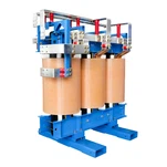
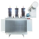
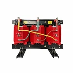
The choice has not changed much, and that is the point. An indoor electrical room inside a data hall almost always means dry type, cast resin or VPI, because there is no oil containment, no bunding and no fire separation to design around. A stand-alone yard or pad, where the footprint is free and the ambient is brutal, still favors oil immersed on cost per MVA and overload capability.
Three practical rules we use on these projects. If the room is already built, cable entry and footprint decide the order of preference long before price does. If the hall is in a market with high seismic demand, the anchorage detail matters more than the cooling class. And if the client's fire strategy assumes dry type means zero fire load, correct that assumption early - cast resin does not burn like oil, but it is not inert.
What We Build, and What We Ask Before We Quote
Ryan Electric has manufactured transformers since 2007 and has been an Eaton joint-venture partner since 2023. The factory runs 120,000 m² with 180-plus sets of production and test equipment and 37 patents, and the units headed to North America ship with UL, cULus and CSA documentation, with IEEE and IEC type-test reports for projects that specify them. Our dry type and oil immersed lines are the ones that sit on the AC side of these halls, from 500 kVA distribution units up to 2.5 MVA and beyond at 34.5 kV.
Before a quotation leaves the factory we ask five things: the rectifier topology and pulse number, the harmonic spectrum at 25, 50, 75 and 100% load, the real load profile including step size and dwell time, the room ambient and site altitude, and whether any units will be paralleled. Answer those five and the rectifier duty transformer specification largely writes itself. Skip them and the buyer ends up paying for a K-factor rating nobody needed, or worse, discovering at commissioning that the derating was never applied.
A Field Note From a 2026 Project
In the first quarter of this year we shipped four 2.5 MVA cast resin units, 34.5 kV delta to 480Y, for an AI hall in the US Midwest. The first design review caught something the tender had not modeled. Two of the four units would run in parallel, and the specification allowed the full impedance tolerance. On paper every unit was 5.75%. On routine test one came in at 5.92% and its partner at 5.61%. That is a 5% mismatch, enough to push a disproportionate share of the load onto the lower-impedance unit and to trip the shared protection on a step load. We re-matched the pairs from measured values before crating, and the EPC changed the tender language for the next phase.
The second finding came from the harmonic study the client ran after the order. At full load the measured 5th harmonic reached 9.8%, which put a general-purpose unit about 18 K hotter than its nameplate rise suggested. The K-13 rating we had quoted covered it; the 100 K winding rise left the margin. Partial discharge on all four units held below 10 pC at 1.5 Um in our test bay in Jiangsu, and the client's witness signed off on ratio, impedance, no-load and load loss before the units were loaded for shipment.
None of that is exotic engineering. It is the difference between buying a transformer and buying the right transformer for a rectifier load.
What to Put in the RFQ
• Rectifier topology and pulse number - 6-pulse, 12-pulse, 24-pulse or active front end
• Harmonic spectrum at 25%, 50%, 75% and 100% load, from the rectifier vendor rather than from a standard table
• K-factor rating and the derating standard behind it (UL 1561 K-rating, IEEE C57.110 calculation)
• Impedance value plus the pairing tolerance for any bank running in parallel
• Ambient, altitude, enclosure (NEMA 1 or 3R) and seismic anchorage requirements
• Certification scope - UL listing versus component recognition, cULus, CSA, and whether the AHJ will require a field evaluation label
If you are specifying an 800 VDC data center transformer now, send us the single-line diagram and the rectifier data sheet. We will return a transformer specification, a test plan and a lead time - not a brochure. Quotes and drawing reviews go through the contact form at www.ryantransformers.com, and the engineering team answers harmonic and impedance questions directly.
About the Author
This article was prepared by the Application Engineering Team at Ryan Electric (Jiangsu Ryan Electric Co., Ltd.), a transformer manufacturer in China supplying oil immersed, dry type and pad mounted transformers to North America, the Middle East, Southeast Asia and Africa since 2007. The team reviews harmonic duty, impedance matching and rectifier-load specifications on custom three phase units, and prepares routine and type test documentation plus UL, cULus, CSA, IEEE and IEC certification packages for data center, utility and industrial projects. Drawing reviews and specification questions can be sent through the contact form at www.ryantransformers.com. Last reviewed: October 2026.
Disclosure: Ryan Electric manufactures and sells the transformers discussed in this article. References to NVIDIA, Vertiv, Delta, UL, CSA, IEEE and IEC describe published specifications and announcements for engineering discussion only; they do not imply endorsement or partnership beyond the Eaton joint venture described above.