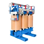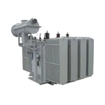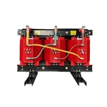


One commissioning call still stands out. Eight diesel gensets started cleanly on the first transfer test, the 13.8 kV yard bus never picked up load, and the generator breakers opened on undervoltage before the plant operator could read the first event on the relay. The machines had done exactly what they were rated to do. The generator step-up transformer between them and the bus had been sized for continuous current only, and nobody had modelled what happens when a 3.5 MVA transformer is switched onto a 3.1 MVA generator.
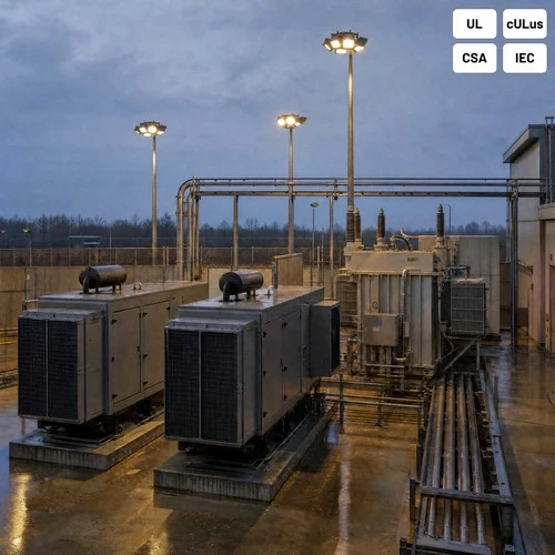
That failure mode is not exotic. As AI halls push single-site loads past 100 MW, more projects split generation and distribution across two voltage levels, and the transformer in the middle gets specified by people who normally buy distribution units. The differences matter: fault current, inrush, grounding, and certification all behave differently when the source is a generator winding instead of a 500 MVA utility network.
Why a Step-Up Transformer Sits Between the Gensets and the Bus
A data center can buy 2.4 kV or 4.16 kV diesel generators and parallel them directly on a medium-voltage bus, or buy lower-voltage machines and lift them to 13.8 kV through unit transformers. Both designs get built every month. The second wins when generator lead time, price, or an existing low-voltage switchgear standard decides the package before the electrical engineer is consulted.
The arithmetic explains the appeal. A 3.125 MVA machine at 2.4 kV carries 752 A of full-load current; the same power at 13.8 kV is 131 A. Cable, busway, and breaker frames scale with that ratio, so lifting voltage close to the generator keeps runs short and lets the yard use standard MV gear. The custom three phase transformer that does the lifting is a small fraction of plant cost, and the source of most commissioning surprises.
Here is the part most buyers miss: this unit is not a distribution transformer with a different turns ratio. It is a source transformer, and several characteristics that make a distribution unit efficient work against you when the upstream impedance is a generator winding.
What the Generator Step-Up Transformer Does to Fault Current
A generator step-up transformer inserts impedance into a circuit that is already impedance-limited. A diesel generator contributes fault current through its subtransient reactance, typically 0.12 to 0.18 per unit for machines in this size range. Add a transformer at 5.75% to 7.5% and the two reactances sit in series. On a 3.125 MVA base, roughly 0.21 per unit limits the 13.8 kV bus to about 600 A of fault current per unit, against some 5,000 A at the generator terminals.
Low fault current is good news for arc flash energy, and it is. The problem is protection sensitivity. A phase overcurrent relay set above load will not see a 600 A bus fault through a 131 A CT circuit with usable margin unless it is voltage-restrained or voltage-controlled (device 51V), with settings computed from the generator decrement curve rather than a utility fault study.
We review those numbers on every generator step-up transformer inquiry we quote, because the coordination gap usually surfaces after the switchgear is built. If the client has no decrement curve, get one from the generator OEM before the transformer impedance is frozen. Choosing 6.5% instead of 5.75% can be the difference between a relay that trips and one that waits until the UPS battery is exhausted.
Energizing From a Dead Bus: Inrush, Voltage Dip, and the Ten-Second Clock
Transformer inrush runs 8 to 12 times rated current for the first cycles and decays over several hundred milliseconds. When the source is a generator, that current comes out of a machine whose terminal voltage is still recovering from a step load. The dip can reach 20% - enough to drop a generator breaker set at 70% pickup, which is exactly what happened in the commissioning call above.
NFPA 110 sets the clock. A Level 1 system is expected to accept load within 10 seconds of a normal-source failure, and every millisecond spent recovering from an inrush event comes out of that budget. On plants with four or more units we recommend sequential energization: close one generator breaker, let the bus stabilize, then close the next. Where the switchgear supports it, a pre-insertion resistor is the cleaner answer. Both are cheaper than a re-test with the owner watching.

The other cheap fix is design discipline. Put the magnetizing inrush current and the excitation curve on the transformer data sheet and hand them to the relay engineer. Plant operators inherit those numbers for twenty years, and nobody can reconstruct them from a finished drawing set.
Winding Connections and Grounding
The usual arrangement for this duty is delta on the generator side and grounded wye on the 13.8 kV side - Dyn11, or a delta-wye with a 30-degree shift. The delta blocks zero-sequence current from the generator, which lets the machine neutral be high-resistance grounded on its own terms. A 5 A resistor at 2.4 kV works out to roughly 277 ohms: small enough to limit stator damage, large enough to stay above capacitive charging current.
On the MV side the wye neutral becomes the grounding source for the whole yard, so that resistor is sized from the downstream ground-fault coordination study, not from the transformer rating. Get the split wrong and a single-phase feeder fault looks like a balanced load to the generator protection.
Resist the wye-wye temptation. It looks simpler on a single-line diagram and it couples generator zero-sequence straight into the MV system, which usually means re-coordinating both sides. For a dry type transformer for data center standby duty, delta-wye also keeps impulse voltage distribution at the line end easier to control in a cast-resin or VPI winding.
Sizing, Temperature Rise, and Harmonic Duty
Size the dry type transformer for data center duty at the generator apparent power and rated power factor, then add margin for what the generator nameplate does not describe: harmonic current from UPS and rectifier loads, altitude above 1,000 m, and ambient above 40 °C. A 10% to 15% margin is normal behind double-conversion UPS. A plant with 6-pulse front ends and no filtering needs a K-factor or derating conversation instead of a bigger box.
The table below is the specification skeleton we work from for a 3.5 MVA unit on a 13.8 kV bus. Values are typical, not universal; what matters is that every row has a downstream consequence.
| Parameter | Typical value for this duty | Downstream consequence |
|---|---|---|
| Rating | 3.5 MVA, 2.4 kV delta - 13.8 kV wye grounded | Headroom over a 3.125 MVA generator for harmonics and 40 °C ambient |
| Impedance | 6.0% - 7.5% on 3.5 MVA base | Sets 13.8 kV fault current and the 51V relay margin |
| Vector group | Dyn11 (30-degree shift) | Blocks generator zero-sequence, defines grounding path |
| Cooling / rise | AN/AF, 115 °C rise, 220 °C insulation | Life at full load; AF stage must be interlocked to load |
| Taps | +/- 2 x 2.5% off-circuit | Aligns generator terminal voltage with yard bus |
| Enclosure | NEMA 1 indoors or NEMA 3R yard | Rain, dust, and rodent protection at the installed location |
| Listing | UL 1562 / cULus, CSA C9 evidence | Accepted at plan review in US and Canadian jurisdictions |
| Tests | Routine per IEEE C57.12.90, witnessed FAT | Baseline for later SFRA and turns-ratio comparison |
Temperature rise deserves its own line, because it is where cheap bids hide. A dry-type unit at 150 °C rise meets nameplate with 220 °C insulation and a shorter life at continuous full load. 115 °C rise costs more copper and buys roughly a decade of thermal margin. For standby duty that runs 50 hours a year, 150 °C is defensible. For a plant that load-tests monthly at 80%, it is not.
Certification: The UL Scope Trap on Medium-Voltage Dry-Type Units
UL 1561 is the standard most buyers name, and on a 13.8 kV unit it is the wrong citation. The published scope from UL Standards & Engagement covers general purpose and power transformers and explicitly excludes units with a nominal primary or secondary rating above 600 V. A medium-voltage step-up unit belongs under UL 1562, with cULus marking where Canada is in scope and CSA C9 evidence behind it.
Design and test references sit alongside the safety listing: IEEE C57.12.01 for dry-type electrical and mechanical requirements, C57.12.90 for the test code, and NFPA 110 for the emergency power system the transformer serves. A submittal that lists UL 1561 against a 13.8 kV winding will come back from review, and it should.
Ryan Electric lists UL and CSA markings on the nameplate and runs routine and type tests to IEEE routines in a 120,000 sq m plant with 180+ sets of production and test equipment, so the data package a US reviewer asks for exists before the RFQ is issued.
What to Put in the RFQ
Six items make quotations for a generator step-up transformer comparable across suppliers. Leave any of them out and you will get six answers that cannot be lined up.
- Generator data. Nameplate kVA, voltage, power factor, and subtransient reactance, plus the decrement curve if the OEM will release it.
- Impedance. Percent on the transformer base, with the acceptable band rather than a single number, so the relay engineer can work inside it.
- Vector group and grounding. Both neutrals stated, with the generator resistor in amps and the MV resistor sized from the ground-fault study.
- Inrush and excitation data. On the data sheet, not buried in a test report issued after shipment.
- Environment. Ambient, altitude, NEMA 1 indoors or NEMA 3R yard enclosure, and whether AN/AF forced cooling is acceptable.
- Listing. UL 1562 with cULus, CSA C9 evidence, IEEE C57.12.01 design basis, and the test witnessed at FAT.
Ryan Electric has built dry-type and oil-immersed transformers since 2007 and has worked as an Eaton joint venture partner since 2023, which is why our submittal packages arrive with test data instead of a brochure. For a custom three phase transformer on a generator bus, we run the inrush against your decrement curve before the price is fixed.
If the standby transformer is still an open line on your single-line diagram, send the generator datasheet and the bus voltage to ryan-transformers.com. You will get an impedance recommendation, a vector group, and a date you can put in the schedule.
About the Author: This article was written by the power transformer engineering team at Ryan Electric, a UL/CSA-certified manufacturer in Jiangsu, China, and an Eaton joint venture partner since 2023, supplying dry-type, oil-immersed, and pad-mounted units to data center, generation, and utility projects across North America, the Middle East, and Southeast Asia.