

Wafer fabs lose more production to a 200-millisecond voltage sag than to most equipment breakdowns. When a tool trips mid-process, the lot inside the chamber is scrap, and requalifying a diffusion or etch step costs hours of production time. That is why the transformer specification on a fab project is written backwards from the ride-through requirement, and why appointing the right UL listed transformer supplier is a decision that starts long before the purchase order.
What a Fab Really Asks of Its Power Distribution
A semiconductor fab is not a heavy industrial load in the usual sense. It is a precision load that happens to draw tens of megawatts. Individually the tool loads are modest, a few hundred kVA each, but there are hundreds of them and they switch with process recipes rather than with shifts. Utility service normally arrives at 13.8 kV or 22.9 kV, steps down to 480 V for main distribution, and then to 208 V at tool level.
What the facility engineer worries about is not kVA. It is whether the secondary voltage stays inside a narrow band while the load moves, and what the transformer does to the voltage the tools see when the upstream network dips. Capacity is being added quickly. SEMI's April 2026 300 mm Fab Outlook projects worldwide 300 mm fab equipment spending to rise 18% to $133 billion in 2026 and a further 14% to $151 billion in 2027, across 404 facilities and lines tracked worldwide. Every one of those lines needs new medium-voltage and low-voltage transformer bays, and most of them sit indoors, which shapes the equipment choice before any technical debate begins.
Voltage Sag Immunity: What SEMI F47 Actually Requires
SEMI F47 is the specification most fab equipment contracts name. It sets minimum voltage sag immunity for processing, metrology and automated test equipment: the tool has to ride through a sag to 50% of nominal voltage for up to 12 cycles at 60 Hz, roughly 200 milliseconds, without interrupting the process. Most utility-generated sags fall in the 3 to 10 cycle range, so a facility built around that curve rides through most of what the grid delivers. The test protocol comes from IEC 61000-4-34, and the requirements are published in the SEMI F47 standard.
SEMI's own note on that specification is worth reading twice: it strikes a balance between sag immunity and increased equipment cost. Translation for a buyer, no transformer and no UPS buys infinite ride-through. What the transformer controls is the voltage the tool starts from and how far it moves. Two numbers decide that. The first is percent impedance. A lower impedance holds the secondary steadier under a step change in load, while a higher impedance keeps fault current inside what the downstream breakers can interrupt. On fab projects the short-circuit study usually sets the ceiling and the design settles under it. The second is tap range, normally plus or minus 2 x 2.5% on the high-voltage winding, which lets the commissioning team centre the secondary voltage at the tool terminals instead of at the transformer bushings. IEEE Std 1100, the IEEE Emerald Book, remains the reference most fab design teams keep for powering and grounding sensitive electronic equipment, and it is the right place to start when the question is where a disturbance came from.
The question we hear most from electrical contractors on fab jobs in Penang and Kulim is not about kVA. It is, what does the secondary voltage do in the first 200 milliseconds, and where is that number in the test file? Measured impedance and no-load loss therefore go on the summary sheet we send with the routine test report rather than being buried inside it.
One second-order effect catches teams during commissioning. Energizing a transformer draws inrush current of several times rated current for a few cycles, and when a row of transformers is commissioned in sequence on the same bus, that inrush can pull the bus voltage down far enough to disturb tools that are already running. Staggered energization handles most of it. It has to be planned, because it will not be discovered until the third unit is switched on.

Harmonics and Non-Linear Tool Loads
A fab's electrical load is mostly power electronics. RF generators, DC power supplies, variable frequency drives on pumps and chillers, and hundreds of switch-mode supplies at tool level all draw non-sinusoidal current. Those harmonic currents do not pass through the transformer for free. They raise eddy-current and stray losses, and the heat appears in the windings, the core clamps and the enclosure rather than on the load meter.
UL 1561 defines K-factor ratings from K-4 to K-20 for exactly this. K-13 and K-20 are common on fab and data center projects, and a higher rating is a statement about the winding's ability to carry harmonic losses without exceeding its temperature rise. It is not a licence to ignore IEEE 519 at the point of common coupling, which still has to be met. The second point buyers miss is the neutral. On 208 V tool-level distribution built from single-phase supplies, triplen harmonics add in the neutral conductor, which is why a 200% rated neutral on the secondary is standard on those systems. If a dry type transformer quote arrives without a single question about the harmonic spectrum, the quote is generic.
How N+1 Redundancy Changes the Transformer Specification
Fab power systems are built as N+1 redundancy or as full 2N. Each load block is normally fed by two transformers, and each unit is sized to carry the whole block on its own with the other out of service. That pushes more capacity into the lineup than the connected load alone suggests, and the usual way to recover it is a second cooling class: a unit rated at one figure with natural cooling and a higher figure with forced-air fans running.
Redundancy also turns two transformers into one electrical machine. Units that will run in parallel need matched voltage ratios, matched impedances and compatible vector groups, and they need to be ordered as a set with test data on each unit. Buying the second unit a year later from whichever factory has capacity is how sites end up with circulating current, uneven load sharing and a spare that cannot be used as a spare. This is the part of the specification where a single UL listed transformer supplier holding the records for both units is worth more than a lower price on one of them.
Dry Type or Oil Immersed Inside a Fab?
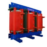
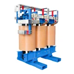
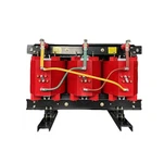
Most transformer decisions inside the building land on dry type, and for good reason. A cast-resin dry type transformer contains no liquid, so it needs no bunding, no vault and no fire separation. That matters when the electrical room sits under a clean room where every square metre of building costs more than the equipment standing in it. Fire review is simpler and maintenance is visual.
| Decision point | Cast-resin dry type | Oil immersed |
|---|---|---|
| Where it belongs in a fab | Indoor electrical rooms, sub-fab and tool-level distribution | Outdoor yard, utility interface, larger blocks |
| Fire and code treatment | No liquid, no bunding or vault, simpler fire review | Separation and bunding required indoors |
| Rating recovery | AN/AF fan cooling, serviceable in occupied buildings | ONAN/ONAF radiators, located outside the room |
| Condition monitoring | Visual inspection and partial discharge checks | DGA, moisture and oil quality programme |
| Typical application | 480 V and 208 V secondary distribution | Main incoming step-down and outdoor capacity |
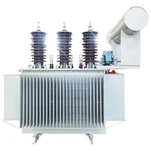
Oil immersed units still belong on the project at the utility interface and in the outdoor yard, and wherever the rating or the ambient conditions push past what an indoor dry type unit serves economically. The choice is a consequence of where the unit sits and how it will be maintained, not a matter of preference.
What to Check Before You Appoint a UL Listed Transformer Supplier
A UL listing is the entry ticket, not the difference between factories. What separates suppliers on a fab project is whether they can produce repeatable data unit after unit. Our routine test sequence on a cast-resin unit covers ratio and polarity, no-load loss, load loss and impedance, applied and induced potential, and a partial discharge measurement, with the pC value printed on the routine test report instead of being summarised as a pass. For a fab, that partial discharge figure is the most useful single indicator of how the cast insulation was made, because it is a process signal as much as a test result.
Ryan Electric has manufactured transformers since 2007 in a 120,000 square metre plant with more than 180 sets of production and test equipment and 37 patents, and has worked as an Eaton joint venture partner since 2023. Units ship with UL, CSA or DEKRA listing as the project requires, with the routine test file signed before the pallet is wrapped. Fab jobs are also one of the few places where a customer sends a witness engineer to the factory. We book a dedicated witness window, run the routine test in front of the visiting engineer and hand over the signed report before packing, which costs far less than an argument six weeks later.

The RFQ Details That Decide Whether the Order Ships Right
Fab transformer enquiries arrive in two flavours. Strong ones list primary and secondary voltage, kVA, impedance range and tolerance, vector group, tap range, cooling classes and both temperature rise figures, harmonic load description, ingress protection, and the site altitude and ambient. Thin ones list kVA and voltage and leave the factory to guess the rest.
The practical version: send the short-circuit study so the impedance window is not guesswork, name the cooling classes because a dual rating changes both price and shipping dimensions, say whether the units will be paralleled, give the harmonic spectrum if a K-factor is required, state the neutral rating if tool-level distribution is single phase, and confirm who will witness the routine test. A UL listed transformer supplier who asks those six questions before quoting has usually built for a fab before.
If a fab project is on your desk and the transformer specification is still open, send it over. We will check the impedance window, the cooling classes and the ride-through assumptions against the SEMI F47 curve, and tell you where the design is exposed before the order is placed rather than after the first shipment.
About the Author. This article was prepared by the engineering and export team at Ryan Electric, a transformer manufacturer established in 2007 and an Eaton joint venture partner since 2023. The team designs cast-resin dry type, oil immersed and custom three-phase transformers for semiconductor, data center and industrial projects, and supports buyers from specification review through factory witness testing.