

Shore Power Transformers: How to Specify HVSC Substations for Port Electrification
Terminal engineers who call us about berth electrification usually open the conversation the same way: "We need about 2 MVA at the quay." Then we ask which vessels will actually call at that berth. The answer can move that number by a factor of ten. A shore power transformer is sized by the ship that plugs into it, not by the load the terminal sees today - and that single distinction is where most first-pass specifications go wrong.

What a Shore Power Transformer Does That a Distribution Unit Cannot
Start with the architecture. At a major port the utility feed can arrive at anything from 34.5 kV up to 230 kV, and a bulk power substation inside the port steps it down to a medium-voltage shore distribution bus. From there each berth gets a dedicated transformer that brings the voltage to 6.6 kV or 11 kV and feeds the cable management system that carries power to the ship. Once the connection is made, the vessel shuts down its auxiliary generators and the terminal takes over the load. Owners call this cold ironing or onshore power supply (OPS); the standards call the whole arrangement a high voltage shore connection (HVSC) system, and the transformer underneath it is a different animal from a distribution unit.
The transformer is not there for voltage conversion alone. It is the galvanic isolation barrier between the shore network and the ship's electrical system. Standard practice, and the arrangement most specifications are written around, is one dedicated transformer per berth with one ship connected at a time, so that grounding problems, stray currents, or faults elsewhere in the port cannot reach the vessel and confuse its ground fault protection.
The governing document is IEC/IEEE 80005-1, developed jointly by IEC, ISO, and IEEE. It covers high-voltage shore distribution, shore-to-ship connection and interface equipment, transformers and reactors, semiconductor and rotating frequency converters, and the control, monitoring, and interlocking systems that tie a berth together. It applies to ships that need 1 MVA or more, or ships with a high-voltage main supply; low-voltage shore connection sits in a separate part of the series. The standards record is public on the IEEE 80005-1 standard page - useful evidence when a utility or a classification society asks where a requirement came from.
Regulation is what turns this from engineering theory into a construction schedule. California's At Berth Regulation has required container, reefer, and cruise vessels to use an approved emission control strategy at regulated terminals since January 2023, extended the requirement to Ro-Ro vessels at all regulated terminals and to tankers at Los Angeles and Long Beach from January 2025, and will extend it to tankers at every regulated terminal from January 2027. Shore power is the route most terminals take. The full compliance schedule is published on the CARB At Berth Regulation page.
Sizing by Vessel Type: The Power Numbers Behind Every Berth
Here is the part buyers underestimate: the vessel mix sets the rating, not the terminal's own demand. Berth power demand in the standard spans a wide band.
| Vessel type | Berth voltage | Power demand at berth |
| Cruise ships | 6.6 kV or 11 kV | 16–20 MVA |
| Container ships | 6.6 kV | 7.5 MVA |
| LNG carriers | 6.6 kV or 11 kV | 10.7 MVA |
| Ro-Ro ships | 11 kV | 6.5 MVA |
| Tankers | 6.6 kV | 7.2 MVA |
Design for the largest vessel in the berth plan, then check whether the smaller calls stay economical to serve. A unit sized for cruise traffic sits at light load through a Ro-Ro visit and still carries close to its full no-load loss, which is the subject of the next section.
Overload capability also matters more here than in a standard distribution application, because berth load arrives in steps. Cold ironing involves two synchronizing operations per call - one to transfer the ship's auxiliary load to shore, one to hand it back at departure. Forced-air cooling gives you documented headroom on top of the nameplate: for dry-type units roughly 33% additional capacity up to 3.75 MVA and about 25% above that; for liquid-immersed units about 12% up to 2.5 MVA and 25% above it. The loading guides behind those numbers are IEEE C57.96 for dry type and IEEE C57.91 for liquid-immersed units. A supplier who cannot produce load-capability curves for your duty cycle is a supplier you will end up arguing with later.
No-Load Loss Is a 24/7 Line Item for Shore Power Transformers
A distribution transformer earns its losses back as load grows. A berth transformer does not get that luxury. It stays energized between vessel calls, sometimes for days, so no-load loss becomes the largest energy item in the asset's operating life.
Do the arithmetic before comparing quotations. A unit with 8 kW of no-load loss energized 8,000 hours a year consumes roughly 64,000 kWh. At an industrial rate of $0.10/kWh that is about $6,400 a year, or roughly $160,000 across a 25-year service life - before load losses and before maintenance. Your tariff will differ; the ordering will not. That cost structure separates onshore power supply projects from ordinary industrial transformer purchases, and it is why we ask for the capitalized loss evaluation the owner intends to apply and design the core and winding around it.
Frequency, Galvanic Isolation, and Grounding: Three Details That Sink Projects
Frequency comes first. Most ships are ordered with 60 Hz electrical systems, so a port fed by a 50 Hz utility needs frequency conversion ahead of the shore-side transformer. Skip that check and the berth is incompatible with the fleet it was built to serve - an expensive discovery at commissioning.
Isolation comes second. In HVSC design the dedicated transformer is the isolation barrier, and it cannot be shared between two berths to save money. Classification societies publish their own acceptance criteria on top of the joint standard, so a peer-reviewed review of IEC/IEEE 80005-1 alongside class society guidance is a useful cross-check when the technical specification has to survive third-party review. One such study is worth keeping in the project file: Navigating Safety and Compliance in High Voltage Shore Connection Systems.
Grounding comes third, and this is where the engineering gets specific. The berth is designed as a high-resistance grounded system with a neutral grounding resistor, and the resistor rating follows the charging current of the combined shore and ship system:
R_N = E_LN / (1.25 × I_C)
where R_N is the neutral grounding resistor, E_LN is the line-to-neutral voltage, and I_C is the total charging current of the shore and ship system combined, with a 1.25 factor applied to cover measurement uncertainty. The resistor is monitored continuously for open and short circuit conditions, and the breakers open on both sides of the connection if that monitoring fails. Use a borrowed charging current instead of a calculated or measured one and the berth develops transient overvoltages that damage equipment on both sides of the cable.

Protection Devices and Safety Hardware Buyers Forget to Specify
The transformer is the simple part of a berth specification. The protection and interface package is where projects lose time.
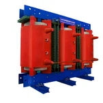
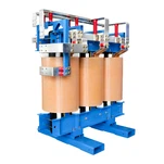
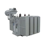
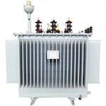
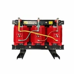
On the transformer itself, a dry-type cast-coil unit needs winding thermal protection (device 49W). An oil-immersed unit adds winding temperature, oil temperature, and oil level devices plus sudden-pressure and pressure-relief protection. On the secondary side the package typically includes overcurrent and neutral overcurrent, overvoltage and undervoltage, reverse power, negative-sequence current and voltage, over and under frequency, and a synchronism check before the ship's supply is paralleled with shore power.
At the cable interface, the plug and receptacle assemblies are rated 350 A or 500 A at both 6.6 kV and 11 kV. Each connector carries three power pins, one ground pin, and two pilot pins, and the ground and pilot circuits make last and break first - which is what keeps an operator safe while a cable is being connected. Kirk-key interlocks link the receptacle cover, the grounding switch, and the main disconnect so the cable is discharged before it is touched, and the cable management system uses safety limit switches to stop a departing ship from pulling the cable and plug apart under load.
Ryan Electric's Approach to Shore Power Transformer Packages
Berth specifications reach us in every format. Some buyers send a complete OPS package from a system integrator; others send three lines of text and a vessel list. Our factory in Jiangsu has built transformers since 2007, with a 120,000 m² manufacturing base, more than 180 sets of production and test equipment, and 37 patents in the portfolio. Since 2023 Ryan Electric has operated as an Eaton joint venture partner. Our certifications cover UL, CSA, IEEE, DEKRA, CNAS, and CE - the file that matters when a port's shore substation is inspected under North American electrical codes or audited by a classification society.
Units for berth projects go through the same routine test regime as our utility transformers: ratio, winding resistance, applied and induced voltage, no-load and load loss, with temperature-rise data recorded during type testing, against ANSI/IEEE C57.12.90 and IEC 60076-1 test procedures. Where a quay-side installation is specified we build liquid-immersed units with sealed oil preservation and corrosion protection agreed for the exposure class. Where the transformer sits indoors or in a ventilated substation room, cast-resin dry-type units are usually the better answer.
One enquiry from last year makes the sizing point better than any brochure. A terminal upgrading a single berth sent a specification for a 3 MVA dry-type unit. Further down the same document, their vessel plan included occasional cruise calls - and a cruise ship draws up to 20 MVA at 6.6 kV. The specified transformer would have been undersized by a wide margin on exactly the vessel class that most needed shore power. We quoted two configurations: a single unit sized for the cruise call, and a phased arrangement with a second transformer bay prepared for future berths.
Planning a Berth Electrification Project?
Five items decide the rating, the price, and the schedule: the vessel mix and the number of berths; the utility voltage and frequency at the port, and whether frequency conversion is needed; the certification target for the shore substation; whether the unit sits indoors or on the quay; and the loss evaluation figure the owner wants applied. Send those to our engineering team through ryan-transformers.com and we will come back with a rating recommendation for your shore power transformer, a loss comparison, and a production date that holds.
About the Author: This article was written by the engineering team at Ryan Electric, an Eaton joint venture partner and UL/CSA-certified transformer manufacturer in Jiangsu, China, serving port, utility, data center, and industrial clients across North America, the Middle East, Southeast Asia, and Africa.