

When a 25 MVA 115 kV/13.8 kV substation transformer operates under heavy summer peak loading, the difference between reliable decades-long service and catastrophic insulation degradation comes down to a few millimeters of dial deflection on the control cabinet door. Transformer paper insulation loses mechanical tensile strength exponentially when subjected to excessive thermal stress. For utility substation engineers and plant electrical maintenance managers, selecting, configuring, and calibrating the transformer winding temperature indicator (WTI) alongside the oil temperature indicator (OTI) is the primary line of defense against thermal aging, dielectric oil breakdown, and premature transformer failure.
Top-Oil vs. Winding Hot-Spot: Understanding Transformer Thermal Dynamics
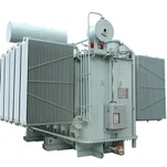
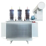
In liquid-immersed power transformers, heat generated by electrical losses (load losses in copper windings and no-load core losses) transfers into surrounding dielectric fluid before circulating through cooling radiators. The oil temperature indicator measures the bulk dielectric liquid temperature at the hottest accessible layer-typically inside a thermowell located at the top of the transformer main tank cover. However, top-oil temperature lags significantly behind rapid winding thermal transients because of the substantial thermal time constant of bulk transformer oil, which typically ranges from 2 to 4 hours in medium and large substation units.
Direct measurement of copper conductor temperatures in energized high-voltage windings presents substantial dielectric isolation challenges. While embedded fiber-optic probes provide direct real-time measurements, mechanical Bourdon-tube and bellows-type dial instruments remain the mandatory, fail-safe industry standard for operating cooling fans, circulating pumps, and emergency protection trip circuits. The transformer winding temperature indicator simulates the hottest conductor temperature-the winding hot-spot-by combining bulk top-oil temperature with a calibrated thermal gradient proportional to the load current squared. Maintaining operating temperatures within strict IEEE C57.91 temperature limits ensures that Kraft paper and thermally upgraded cellulose insulation do not suffer irreversible thermal aging.
How Thermal Imaging CTs and Gradient Heaters Simulate Hot-Spot Temperatures
The operational core of an indirect transformer winding temperature indicator is the thermal simulation circuit. A dedicated bushing current transformer-commonly referred to as a thermal imaging CT-is installed over one of the loaded phase bushings (typically on the secondary low-voltage winding carrying maximum continuous rated load current). The secondary current from this CT (standardized at either 5 A or 1 A) is routed through an adjustable matching resistance circuit and injected into a calibrated heating resistor (gradient heater coil) embedded inside the WTI sensor bulb or thermowell assembly.
As electrical load increases, secondary current circulating through the heating coil generates localized heat, elevating the capillary bulb temperature above surrounding top oil. The resulting temperature dial reading reflects the composite equation: Tw = Ttop_oil + ΔThs, where ΔThs represents the calculated winding-to-oil thermal gradient. According to guidelines from the IEEE Standards Association under IEEE Std C57.91 and IEEE Std C57.12.00, this simulated gradient must precisely match the measured thermal rise established during the factory temperature rise test (heat run test) at rated nameplate capacity.
Critical Differences: WTI vs. OTI Technical Comparison
Specifying substation transformer instrumentation requires a clear engineering understanding of the operational and functional distinctions between oil and winding monitoring channels. The following comparison table details sensor mechanics, input sources, and control functions:
| Engineering Parameter | Oil Temperature Indicator (OTI) | Winding Temperature Indicator (WTI) |
|---|---|---|
| Sensing Medium | Top-tank dielectric mineral oil or natural ester fluid | Top-oil + simulated thermal gradient from Bushing CT |
| Thermal Input Signal | Pure convective fluid temperature in thermowell | Thermowell oil heat + internal gradient heater resistor |
| Secondary Input Source | None (Capillary bulb only) | Bushing thermal imaging CT (1 A or 5 A secondary) |
| Primary Control Function | Bulk dielectric liquid thermal health & Overtemp trip | Winding hot-spot tracking & Multi-stage fan/pump control |
| Contact Switch Stages | 2 to 3 microswitches (Alarm, Trip, Spare) | 4 microswitches (Fan Bank 1, Fan Bank 2, Alarm, Trip) |
| Governing Standard | IEEE C57.12.00 (55°C / 65°C Top-Oil Rise Limits) | IEEE C57.91 temperature limits (110°C Continuous Hot-Spot) |
Calibrating the Heating Gradient: Lessons from Substation Commissioning
A frequent cause of spurious transformer thermal alarms or delayed cooling fan engagement during field commissioning is incorrect potentiometer calibration on the WTI dial. During the commissioning of a 25 MVA 115 kV/13.8 kV substation transformer in Texas, our field engineering team identified a case where the WTI indicated 98°C while calibrated SCADA RTDs read only 80°C top oil under a moderate 70% load. Physical inspection revealed that the adjustable shunt potentiometer across the heating element was left at its maximum 100% factory default setting rather than calibrated to the certified factory heat run test gradient of 14.2°C at 100% rated current.
To correctly calibrate a transformer winding temperature indicator, commissioning technicians must calculate the exact secondary current output of the thermal imaging CT at rated transformer MVA and adjust the shunt resistor dial so that the heating coil generates precisely the required gradient corresponding to the load current ratio: ΔThs × (Iload / Irated)2m, where m is the winding cooling exponent defined in IEEE C57.91 (typically 0.8 for ONAN and ONAF cooling modes). International standards published by the International Electrotechnical Commission (IEC) in IEC 60076-2 specify similar temperature rise verification protocols for liquid-immersed transformers to ensure precise protection coordination.
Setting Multi-Stage Microswitch Contacts for Optimal Cooling and Asset Protection
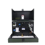
Modern WTI and OTI gauges are equipped with independently adjustable, snap-action microswitches (typically Form C SPDT or DPDT contacts rated for 10 A at 120/240 VAC or 0.5 A at 125 VDC). Establishing proper setpoints avoids unnecessary auxiliary power consumption from cooling fans while strictly enforcing IEEE C57.91 temperature limits:
• Stage 1 Forced Air Cooling (FA1 / Fan Bank 1): Set WTI to 80°C–85°C (or OTI to 70°C). Engages the primary cooling fan bank during rising load cycles before internal heat builds up.
• Stage 2 Forced Air / Oil Pump Cooling (FA2 / FOA): Set WTI to 90°C–95°C (or OTI to 80°C). Activates auxiliary fan groups or forced-oil circulating pumps to halt rapid temperature acceleration.
• High Temperature Alarm: Set WTI to 105°C (or OTI to 85°C–90°C). Dispatches warning supervisory alerts to the substation SCADA master, giving operators time to shed non-critical load without interrupting service.
• Emergency High-High Trip: Set WTI to 120°C–125°C (or OTI to 100°C–105°C). Initiates lockout relay (86T) tripping to isolate the transformer before cellulose paper experiences catastrophic thermal runaway and accelerated aging.
Engineering Precision at Ryan Electric: Factory Heat Run Testing and Calibration Rigor
At Ryan Electric's 120,000 m² advanced manufacturing facility, every liquid-immersed substation, pad-mounted, and power transformer undergoes rigorous temperature rise testing in our CNAS-certified testing laboratory. Equipped with over 180 sets of high-precision testing apparatus and automated data acquisition systems, our engineering team measures winding resistance variations using the Kelvin four-wire method to calculate exact average temperature rises and determine winding-to-oil gradients down to 0.1°C resolution.
Since 2023, as an official joint-venture partner of Eaton, Ryan Electric integrates globally recognized control instrumentation-including Qualitrol, AKM, and Messko temperature indicators with integrated 4–20 mA transducers, dual PT100 RTDs, and RS-485 Modbus communications for direct smart grid and SCADA connectivity. Every WTI heating unit is pre-calibrated and matched to its specific bushing CT ratio before leaving the factory, accompanied by certified calibration test curves.
Specifying WTI and OTI Instrumentation for Your Next Substation Project
When preparing technical procurement specifications for medium and high-voltage power transformers, include explicit requirements for temperature monitoring systems. Specify whether the WTI requires dual capillary systems, resettable maximum temperature drag pointers, remote RTD inputs, or integrated optical fiber modules for hybrid monitoring. Ensure that the thermal imaging CT accuracy class and secondary burden rating are coordinated with the heater circuit impedance to eliminate measurement saturation under overload conditions.
For engineering support, custom temperature indicator configurations, or technical inquiries regarding transformer thermal design and compliance with IEEE C57.12.00, contact the Ryan Electric technical team at ryan-transformers.com or submit your specification to our application engineering group.
About the Author: Marcus Vance is a Senior Substation Instrumentation and Thermal Design Specialist at Ryan Electric with over 16 years of experience in high-voltage power transformer testing, protection coordination, and substation asset health monitoring.