

When an engineering team at an Ashburn, Virginia data center colocation facility energized a newly installed server hall last year, their monitoring system threw high-temperature alarms within twenty-four hours of bringing the server racks up to 80% capacity. The transformers were operating below their nominal kVA nameplate rating, yet the winding temperature indicators were already climbing toward dangerous limits. The root cause was not an electrical overload in root-mean-square amperes, but non-linear harmonic currents generated by thousands of switch-mode power supplies and variable frequency drives. Selecting the correct K-factor transformer sizing is no longer an optional upgrade for commercial facilities-it is the single most critical specification deciding whether your power distribution infrastructure survives decades of severe harmonic distortion or burns out in its first year.
Standard distribution transformers are engineered to supply purely sinusoidal 50 Hz or 60 Hz currents. However, modern mission-critical facilities, electric vehicle charging hubs, semiconductor plants, and AI computing clusters operate almost entirely on non-linear loads. These loads generate intense harmonic frequencies that multiply internal winding losses, overheat neutral conductors, and degrade insulation systems. Understanding how to calculate and specify a K-factor dry-type transformer ensures your facility maintains high energy efficiency, complies with thermal standards, and eliminates catastrophic downtime.
Understanding Harmonic Distortion and Why Standard Transformers Overheat
To understand why standard transformers fail when feeding non-linear loads, one must examine where internal losses occur. Total transformer load losses consist of fundamental frequency I²R resistance losses, winding eddy current losses, and stray load losses in the structural tank, core clamps, and enclosure. In a standard linear environment, winding eddy current losses account for roughly 5% to 10% of total load losses at fundamental frequency.
When non-linear loads draw distorted currents, the high-frequency harmonic components dramatically increase these parasitic losses. According to fundamental electromagnetic principles, winding eddy current losses increase proportionally to the square of the harmonic order multiplied by the square of the harmonic current magnitude (PEC ∝ Ih² × h²). For instance, a 7th harmonic current of 20% nominal amplitude generates (0.20)² × 7² = 1.96 times the baseline fundamental eddy current loss in that specific conductor volume. These concentrated harmonic eddy current losses produce localized thermal hot spots deep within the high-voltage and low-voltage windings, accelerating paper and resin thermal aging at an exponential rate.
Furthermore, single-phase non-linear power supplies generate triplen harmonics-specifically the 3rd, 9th, 15th, and 21st harmonic orders. Unlike balanced fundamental currents which cancel to zero at the neutral junction of a four-wire wye secondary, triplen harmonics are in phase with each other and sum algebraically in the neutral conductor (IN ≈ √3 × I3). In high-density server halls, neutral current frequently reaches 130% to 170% of the phase current magnitude, causing standard neutral busbars and terminal connections to overheat and fail if proper triplen harmonics neutral sizing is not engineered from the factory.
The ANSI/IEEE C57.110 K-Factor Equation Explained
To standardize transformer capability under non-sinusoidal currents, the Institute of Electrical and Electronics Engineers established the K-factor calculation methodology defined in IEEE standards and C57.110 guidelines. K-factor is a numerical weighting factor reflecting the heating effect of harmonic load currents relative to standard sinusoidal current.
The mathematical formula for calculating the load K-factor is expressed as:
K = Σ [ Ih² × h² ] / Σ [ Ih² ]
Where h represents the harmonic order (1st, 3rd, 5th, 7th, etc.) and Ih represents the true root-mean-square current at harmonic order h expressed as a per-unit fraction of total RMS load current. A pure sinusoidal current has only a fundamental component (h=1, I1=1.0), resulting in a baseline K-factor of exactly 1.0. As harmonic distortion increases, the higher-order components rapidly escalate the numerator, driving the K-factor value upward to K-4, K-13, K-20, or even K-30.
It is worth noting that European and international engineering standards often reference the Factor-K derating approach defined in BS 7821-4 and IEC 60076. While European Factor-K is calculated differently (where a lower factor indicates greater derating), North American engineering practice universally specifies ANSI/IEEE K-factor ratings where higher numbers represent greater harmonic withstand capability.
K-Factor Classification Spectrum: K-1, K-4, K-13, and K-20 Load Profiles
Specifying the right transformer requires matching the calculated load profile with standardized industrial K-factor classes. Overspecifying adds unnecessary capital expenditure, while underspecifying leads to thermal tripping, shortened equipment lifespan, and voided manufacturer warranties.
| K-Factor Rating | Harmonic THD-I | Typical Applications | Winding & Neutral Design | Thermal Headroom |
|---|---|---|---|---|
| K-1 | < 5% | Incandescent lighting, resistance heaters, linear induction motors, standard HVAC fans | Standard winding conductors, 100% rated neutral busbar | Baseline |
| K-4 | 15% – 35% | Commercial office buildings, school classrooms, HID lighting, telecommunication PBX rooms | Multi-strand conductors, 150% rated neutral busbar, electrostatic shield | +25% eddy loss tolerance |
| K-13 | 35% – 50% | Enterprise data centers, hospital MRI/CT suites, broadcast studios, high-density server halls | Foil / CTC transposed windings, 200% double-capacity neutral bus, copper shield | +100% eddy loss tolerance |
| K-20 / K-30 | > 50% | AI GPU server farms, multi-MW EV charging plazas, SCR motor drives, solid-state furnaces | Segmented parallel transposed foil, 200% neutral, low flux density core, Class 220 Nomex | +200% eddy loss tolerance |
Core Construction Differences in K-Factor Dry-Type Transformers
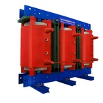
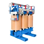
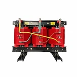
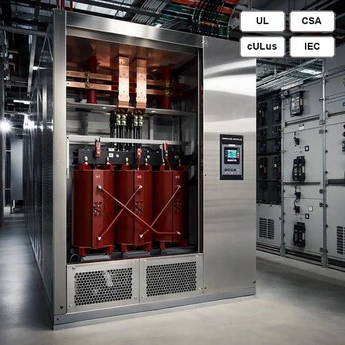
A high-performance cast resin dry-type transformer or vacuum pressure impregnated (VPI) unit designed for high K-factors is not merely an oversized standard transformer. It incorporates specialized metallurgical, geometric, and insulation engineering enhancements:
1. Continuous Transposition and Multi-Strand Foil Windings: To suppress high-frequency skin effect and proximity effect, primary and secondary coils use parallel thin-strip copper foil or Continuously Transposed Cable (CTC). Subdividing conductors into smaller insulated strands dramatically lowers cross-sectional eddy current circulating paths.
2. 200% Rated Double-Capacity Neutral Assembly: Because triplen harmonics concentrate in the neutral return, K-13 and K-20 transformers feature full-length copper neutral busbars and terminal connection lugs sized for 200% of the nominal line phase current, completely eliminating terminal overheating.
3. Reduced Core Flux Density and Premium Steel Laminations: Harmonic voltage components and non-linear DC bias can push magnetic cores into non-linear saturation regions. Ryan Electric engineers design magnetic cores using high-permeability, grain-oriented silicon steel operating at conservative flux densities (1.50 to 1.58 Tesla instead of conventional 1.72 Tesla), maintaining low excitation currents and acoustic noise.
4. Electrostatic Ground Shields: A continuous copper electrostatic Faraday shield placed between the high-voltage and low-voltage windings provides effective attenuation against common-mode electrical noise, switching spikes, and high-frequency transients.
5. Class 220 Nomex Thermal Insulation Systems: Utilizing premium DuPont Nomex insulation rated for 220°C continuous service while designing the transformer for an 80°C or 115°C temperature rise over a 40°C ambient creates an extra 35°C to 70°C thermal safety margin, protecting the asset during extreme seasonal loading spikes.
Engineering Field Experience: Sizing K-13 Units for a 1,500 kVA Colocation Facility
In our factory engineering experience, real-world field harmonic measurements consistently reveal why conservative specifications pay dividends. When our application engineers assisted an engineering contractor in sizing step-down transformers for a 1,500 kVA 480V–208Y/120V data hall in Northern Virginia, the initial harmonic audit measured a current total harmonic distortion (THD-I) of 42.6% under normal business operations.
The harmonic spectrum showed a 19.2% third harmonic, 28.4% fifth harmonic, 14.1% seventh harmonic, and 8.6% ninth harmonic. Running these exact numbers through the ANSI/IEEE C57.110 equation produced a calculated load K-factor of 11.4. Had the facility installed a standard K-1 transformer, winding eddy losses would have escalated by over 160%, driving internal hot-spot temperatures past 152°C and triggering thermal protection relays.
By deploying a custom Ryan Electric K-13 rated Cast Resin dry-type transformer built with 200% neutral busbar capacity, 115°C temperature rise Class 220 insulation, and full electrostatic shielding, the measured full-load steady-state hot-spot temperature rise was held to just 81.8°C. The system operated with zero nuisance trips, minimal acoustic hum, and total thermal stability.
Why Ryan Electric K-Factor Transformers Deliver Long-Term Reliability
Ryan Electric operates a modern 120,000 m² manufacturing base equipped with over 180 sets of precision production and testing machinery, supported by 37 technical patents. Since 2023, Ryan Electric has operated as an authorized joint venture partner with Eaton, manufacturing high-reliability power and distribution transformers for global markets.
Every K-factor dry-type unit leaving our factory undergoes comprehensive routine and type testing according to UL standards and safety certifications (UL 1561 / UL 1562), CSA C22.2, and IEEE standards. In our accredited test bay, we validate insulation resistance, winding dissipation factor (Tan Delta), partial discharge (< 10 pC), and full-load temperature rise under simulated harmonic current injection.
Whether you require a compact K-13 unit for an indoor electrical vault or a heavy-duty K-20 Cast Resin transformer designed to meet the latest U.S. Department of Energy efficiency requirements, our engineering team delivers precision-engineered solutions with customized dimensions, top or bottom cable entry, and integrated digital temperature controllers.
Practical Procurement Checklist and Sizing Recommendations
When preparing electrical equipment specifications for new construction or facility retrofits, follow these practical engineering rules of thumb:
• Conduct a Comprehensive Harmonic Power Quality Audit: Measure existing feeder harmonic spectrum or perform detailed load modeling with ETAP or SKM to identify expected THD-I and dominant harmonic orders before finalizing your procurement package.
• Always Apply a 20% Growth Margin: If your calculated load K-factor is 9.5, do not specify K-9 or round down to K-4. Standardize on the next standard industrial class-K-13-to accommodate future server upgrades or EV charger expansions.
• Mandate 200% Neutral Sizing in Specifications: Explicitly state that secondary neutral busbars, terminal pads, and neutral cable landing lugs must be rated for at least 200% of nominal phase current to prevent triplen harmonic overheating.
• Select 115°C or 80°C Temperature Rise: Combining Class 220 Nomex insulation with an 80°C or 115°C temperature rise rating reduces energy losses, lowers cooling HVAC demand, and substantially extends transformer operating life.
• Insist on Factory Test Witnessing and Certification: Verify that your supplier provides certified factory test reports verifying compliance with UL 1561, CSA C22.2 No. 47, and IEEE C57.110 standards.
Contact Ryan Electric's senior engineering team today to review your electrical one-line diagrams, calculate exact K-factor requirements, and receive a competitive technical proposal with industry-leading delivery lead times.
About the Author: David Chen is a Senior Electrical Application Engineer at Ryan Electric with over 16 years of experience in dry-type and liquid-immersed transformer design, harmonic mitigation, and mission-critical power distribution systems across North America and Southeast Asia.