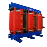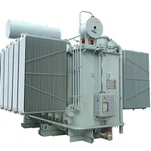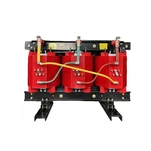


When industrial electrical contractors and utility procurement engineers evaluate bids for medium-voltage substations, the lowest upfront equipment price frequently conceals an expensive operational trap. Over a standard 30-year operational lifecycle, the electrical losses dissipated by an energized distribution or power transformer often cost three to five times the original factory purchase price. For example, in a continuous 2500 kVA 13.8 kV to 480 V manufacturing substation, an unoptimized unit dissipating merely 1.5 kW of extra continuous core loss burns over $35,000 in unrecoverable electricity bills at North American industrial utility rates. Evaluating bids strictly through a rigorous transformer total owning cost (TOC) methodology transforms transformer selection from a short-sighted capital expenditure into a structured lifecycle investment that guarantees measurable energy savings.
In our manufacturing test bays and technical consulting engagements across North America and Southeast Asia, we routinely witness procurement teams transitioning from bare purchase price comparisons to total capitalized cost evaluation. By quantifying both transformer no-load loss and load loss over the expected service life, engineering managers can mathematically justify high-grade magnetic cores, optimized copper conductor sizing, and high-efficiency winding geometries.
What Is Transformer Total Owning Cost (TOC) and Why Purchase Price Misleads Buyers
The fundamental premise of transformer total owning cost is that an electrical transformer operates as an active energy-converting asset whose operational losses must be capitalized into present value currency at the exact moment of procurement. Electrical power utilities and industrial EPCs express this relationship using the standardized IEEE capitalization equation: TOC = Purchase Price + (A × P0) + (B × Pk). In this formulation, Purchase Price represents the initial invoice and freight cost, P0 represents the guaranteed transformer no-load loss in kilowatts (kW), Pk represents the guaranteed load loss in kilowatts at rated temperature and load, while A and B represent site-specific loss capitalization factors in dollars per kilowatt ($/kW).
Here is the critical distinction that procurement teams must grasp: transformer no-load loss-also known as core or iron loss-occurs continuously 8,760 hours per year whenever the transformer is energized from the primary grid, completely independent of whether the secondary circuit is carrying zero load or full rated current. In contrast, load loss-consisting of I²R winding resistance losses and stray eddy current losses-varies with the square of the operational load current. Because continuous core dissipation exerts a relentless compound cost over decades, the capitalization A factor is invariably three to five times larger than the B factor.
Deriving Capitalization A and B Factors: The Mathematical Model Behind Loss Evaluation
To establish defensible evaluation figures, engineers rely on the comprehensive mathematical frameworks defined in the IEEE C57.120 Guide for Loss Evaluation (IEEE Guide for Loss Evaluation of Distribution and Power Transformers and Reactors). The A factor translates every kilowatt of continuous core loss into its cumulative present worth over the entire expected asset lifespan n (typically 20 to 30 years) under a designated internal discount or interest rate i and levelized electricity energy cost C ($/kWh):
A Factor Formula: A = C × 8,760 × [((1 + i)^n - 1) / (i × (1 + i)^n)] + Capacity Charge Component ($/kW). For a facility facing an industrial tariff of $0.11/kWh, a 6% discount rate, and a 25-year design horizon, the uniform present worth factor equals 12.783, resulting in an A factor of approximately $12,320 per kilowatt of continuous core loss. Even under conservative commercial assumptions, modern utility A factors typically range between $5,000/kW and $11,000/kW.
The B factor for transformer loss evaluation weights the load loss by the facility loading profile, incorporating the peak load ratio (P_peak / P_rated), the root-mean-square loading factor, and the system loss factor (F_ls = 0.15 × LF + 0.85 × LF²).
B Factor Formula: B = C × 8,760 × (Load Factor_equivalent)² × [((1 + i)^n - 1) / (i × (1 + i)^n)] + Peak Demand Charge. In data centers, renewable solar step-up stations, and industrial manufacturing plants with average loading factors between 40% and 65%, the resulting capitalization A and B factors yield B values between $1,500/kW and $3,800/kW. When bids are evaluated with these factors, an efficient transformer with slightly higher initial pricing easily wins the competitive tender.
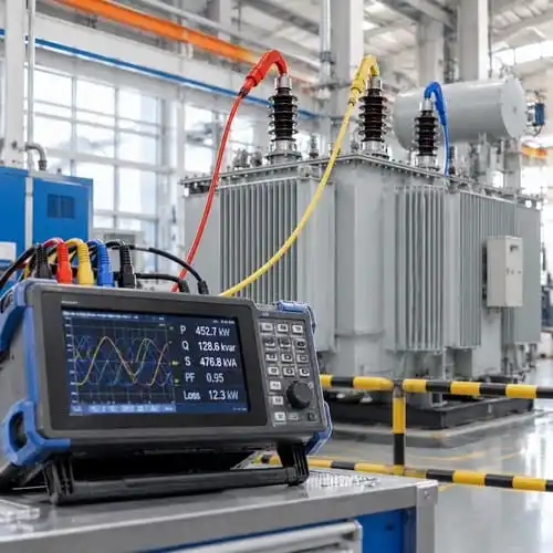
No-Load Loss vs. Load Loss Sizing: Materials and Engineering Trade-Offs
Achieving superior transformer total owning cost requires structural innovations in the magnetic core and electrical winding architecture. To aggressively drive down core dissipation, advanced transformer manufacturers employ high-permeability, laser-scribed Grain-Oriented Silicon Steel (CRGO) such as 20Q085 or 23Q110, or ultra-low-loss amorphous alloy ribbons. Furthermore, adopting fully automated 45-degree mitered step-lap core stacking eliminates air-gap flux crowding at the corner joints, reducing core excitation current and cutting transformer no-load loss by 18% to 25% compared to conventional butt-lap laminations.
For winding optimization, controlling load loss requires minimizing both DC copper resistance and high-frequency stray eddy losses. In heavy-current low-voltage windings, utilizing Continuously Transposed Conductor (CTC) or rectangular oxygen-free electrolytic copper (OFC) strip lowers current density below 2.5 A/mm², while electrostatic shielding prevents localized eddy heating caused by stray harmonic leakage flux.
DOE 2029 Efficiency Mandates and TOC Impact on North American Procurement
In North America, loss evaluation is no longer solely an internal financial consideration; it is reinforced by federal regulatory mandates. The U.S. Department of Energy (DOE) Appliance and Equipment Standards (published under 10 CFR Part 431) establish statutory minimum efficiency levels for all distribution transformers installed across the United States. The upcoming DOE 2029 energy conservation standards push efficiency limits higher, requiring medium-voltage liquid-immersed units to reach efficiency thresholds exceeding 99.53% at 50% rated load.
For facility engineers specifying equipment today, purchasing units that merely scrape past legacy DOE 2016 levels exposes projects to premature economic obsolescence and excessive lifetime operational penalties. Aligning technical specifications with aggressive capitalization A and B factors ensures that new installations naturally comply with future grid decarbonization and efficiency baselines.
Real-World TOC Case Study: Standard Efficiency vs. Low-Loss Transformer
To illustrate the practical financial impact of transformer loss evaluation, consider a practical procurement scenario for an industrial facility selecting a 2500 kVA, 13.8 kV to 480 V three-phase pad-mounted transformer. The project engineering team establishes capitalization parameters of A = $8,200/kW for core losses and B = $2,100/kW for winding load losses over a 25-year service period.
| Evaluation Parameter | Bidder A (Standard Unit) | Bidder B (Ryan Low-Loss) | Lifecycle Difference |
|---|---|---|---|
| Transformer Rating / Voltage | 2500 kVA, 13.8 kV - 480 V | 2500 kVA, 13.8 kV - 480 V | Identical Rating |
| Initial Purchase Price | $51,800 | $58,200 | +$6,400 (Bidder B Higher) |
| Guaranteed No-Load Loss (P0) | 3.45 kW | 2.15 kW | -1.30 kW (Bidder B Lower) |
| Capitalized No-Load Cost (A × P0) | $28,290 (at $8,200/kW) | $17,630 (at $8,200/kW) | -$10,660 (Bidder B Savings) |
| Guaranteed Load Loss (Pk) | 21.80 kW | 17.90 kW | -3.90 kW (Bidder B Lower) |
| Capitalized Load Cost (B × Pk) | $45,780 (at $2,100/kW) | $37,590 (at $2,100/kW) | -$8,190 (Bidder B Savings) |
| Total Owning Cost (TOC) | $125,870 | $113,420 | -$12,450 Net Savings (Win) |
As demonstrated in the comparison table, Bidder A appeared $6,400 cheaper on the upfront bid sheet. However, when evaluating the full transformer total owning cost, Bidder B (Ryan Low-Loss design) delivers a net lifecycle savings of $12,450. The initial price premium of $6,400 is fully paid back in less than 2.8 years of continuous operation, after which the facility earns pure operational cost reductions for the remaining 22+ years of equipment life.
How Ryan Electric Optimizes Transformer Loss Profiles and Guarantees TOC Metrics
At Ryan Electric (瑞安电气), our 120,000-square-meter modern manufacturing base operates over 180 advanced production stations and holds 37 utility and design patents dedicated to magnetic efficiency and thermal optimization. Since 2023, Ryan Electric has operated as an official joint-venture partner with Eaton (伊顿), manufacturing high-reliability transformers that adhere to rigorous global quality benchmarks.
Every medium-voltage pad-mounted, substation, and dry-type unit manufactured by Ryan Electric is designed to minimize transformer no-load loss through precision CNC-slit high-grade silicon steel cores and step-lap mitering. During Factory Acceptance Testing (FAT), each transformer undergoes calibrated loss measurement in strict accordance with IEEE C57.12.90 and IEC 60076-1 standards in our CNAS-accredited high-voltage test laboratory. We provide fully certified test reports verifying that guaranteed loss values fall within tight commercial tolerances, backed by our international UL, CSA, cULus, and CE product certifications.
Key Takeaways and Sizing Checklist for EPCs and Utility Buyers
When issuing Request for Proposals (RFPs) for upcoming capital projects, follow this structured checklist to ensure maximum lifecycle value:
1. Publish Site-Specific A and B Factors: Never leave loss evaluation ambiguous. Calculate and provide explicit $/kW figures for core and load losses directly in your inquiry documents.
2. Require Guaranteed Test Tolerances: Specify that manufacturer loss guarantees must comply with IEEE C57.12.00 tolerances (maximum +10% on total losses or +15% on individual components), with financial penalty clauses for exceeding guaranteed limits.
3. Validate Temperature Rise Bases: Ensure that load losses are quoted at the standardized reference temperature (typically 85°C for 65°C rise liquid units, or 145°C for 115°C rise dry-type units).
4. Request CNAS / ISO Certified Test Reports: Mandate that factory loss data be measured using multi-channel precision power analyzers calibrated against national metrology standards.
Ready to optimize your project electrical efficiency? Contact the engineering team at Ryan Electric today to receive a detailed transformer total owning cost capitalization analysis and competitive quotation for your next substation installation.
About the Author: Ryan Electric Senior Applications Engineering Team. Specializing in high-efficiency pad-mounted, substation, and dry-type transformer manufacturing, IEEE/CSA compliance testing, and lifecycle loss capitalization for global utilities and industrial EPCs. For technical inquiries, contact sales@ryantransformers.com or visit https://www.ryantransformers.com.