

Two 25 MVA transformers can sit side by side on the same feeder and behave completely differently. Same kVA. Same impedance. Same efficiency class. The difference is often a component most buyers never put on their RFQ: the transformer tap changer. When we ask customers what they plan to do about voltage fluctuation on their site, the silence on the other end of the line tells us more than any datasheet. This guide explains the two main types, what each one costs to own over twenty years, and exactly what you need to specify before the factory starts winding.
What a Transformer Tap Changer Actually Does
A transformer's voltage ratio is fixed by the turns ratio of its windings. The transformer tap changer exists to change that ratio without rewinding anything: taps are connection points tapped off the high-voltage winding at regular intervals, and moving the connection from one tap to another shifts the ratio by a defined step. On a distribution unit, one standard step is 2.5% - move two steps and you have corrected the output voltage by 5%.
Why does that matter? Because the voltage arriving at your transformer is never exactly the nameplate value. Upstream feeders sag under load, long rural lines drop several percent between a substation and the far end, and generators ride through daily swings. Without a tap changer, a transformer that delivers 480 V at nominal input will deliver something closer to 456 V when the incoming voltage sits 5% low - and motors, drives, and lighting all feel it.
The engineering standards that govern tap changer performance and testing are worth knowing before you buy. In North America, IEEE C57.131-2012 sets the electrical and mechanical requirements for both load tap changers and de-energized tap changers - you can check the scope on the IEEE Xplore page. Internationally, IEC 60214-1 covers the same ground for on-load, off-circuit, and motor-drive tap changers.
De-Energized Tap Changer (DETC): The Workhorse of Distribution
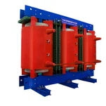
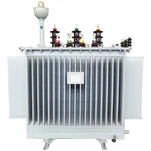
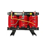
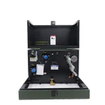
A de-energized tap changer (DETC) is switched only when the transformer is completely isolated - no load, no excitation, no exceptions. Inside an oil-filled unit the switch is a rotating contact on the winding end; on a dry type transformer it is usually a terminal board you reconnect by hand. The common configuration on three-phase pad-mounted and pole-mounted distribution transformers is five positions spanning -5% to +5% in 2.5% steps: that covers the seasonal voltage drift most utilities see without adding a single moving part to normal operation.
Here is a scene from our own loading bay. When we ship pad-mounted units to North America, the DETC leaves the factory set to the neutral position unless the customer's standard specifies otherwise, and we hang an orange tag on the tank that says: verify the tap position by ratio test before energizing. That tag exists because we have seen the aftermath of a tap changed while the unit was live, and because crews sometimes assume the switch position shown on the nameplate matches where the internal contacts actually sit. A two-minute ratio test after any tap change settles it.
The lesson for buyers: a DETC is simple, nearly maintenance-free, and cheap - but it is only useful if someone knows the correct position for your site and checks it before the unit goes hot. Changing the tap later means scheduling an outage, which is the single biggest reason projects move up to an on-load design.
On-Load Tap Changer (OLTC): Regulation Without Dropping the Load
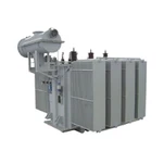
An on-load tap changer (OLTC) does the same job while the transformer stays energized and loaded. Inside the tank, a diverter switch transfers the current between taps fast enough that the supply never breaks; the arc is quenched in oil or inside a vacuum interrupter, and a motor-drive mechanism positions the tap selector. A control relay compares the regulated voltage against a setpoint and commands tap changes automatically, often with line-drop compensation to hold voltage at the far end of a feeder rather than at the transformer terminals.
A typical OLTC specification on a medium-voltage power transformer is ±10% range in 17 positions, with each step at 1.25% of rated voltage. That sounds like a small number, but it is the difference between a plant that runs at 395 V on a hot afternoon and one that holds 400 V through every shift change. IEC 60214-1:2014 defines the performance and test requirements for these devices, including the newer vacuum-type designs - the IEC Webstore page summarizes the scope.
Our clearest example comes from substation units we have supplied for 33 kV rural networks where feeder length pushes daytime voltage swings past 6%. A fixed-tap transformer would hand the end customers whatever the line delivered; a motorized OLTC with an automatic voltage control relay holds the secondary bus inside ±2% through the daily cycle - voltage regulation a fixed-tap unit simply cannot deliver. Before those units left our test bay, our engineers ran a ratio and polarity test at every one of the 17 tap positions, not just the principal tap - because a mis-wired tap selector only shows up when you check every step.
DETC vs OLTC: Side-by-Side Comparison
Here is the comparison we walk buyers through in every technical call:
| Dimension | DETC (De-Energized) | OLTC (On-Load) |
| Operation | Unit must be de-energized | Under load, automatic or remote |
| Typical range | -5% to +5% in 2.5% steps (5 positions) | ±10% in 17 positions (1.25% steps) |
| Cost premium | Small (5-10%) | Significant (15-30%) |
| Maintenance | Minimal; check contacts on outage | Regular: oil/DGA, contacts, motor drive |
| Best fit | Distribution, pad-mounted, stable grids | Substations, industrial plants, weak grids |
| Failure mode | Wrong tap position, human error | Mechanical wear, control mis-set |
| Governing standard | IEEE C57.131 / IEC 60214-1 | IEEE C57.131 / IEC 60214-1 |
The honest rule of thumb we give customers: if your incoming voltage stays inside ±5% and you can tolerate a short outage to change taps, a DETC is the right call and an OLTC is wasted money. If the grid is weak, the feeder is long, or the process cannot tolerate a dip when the tap is adjusted, an OLTC pays for itself in the first voltage event it prevents.
What to Put on Your RFQ (and What to Leave Off)
Before you write "with tap changer" and stop, do the arithmetic.
- Measure the real voltage profile. Log the incoming voltage for two to four weeks, or pull utility data. A spec built on a guess is a gamble either way.
- Match the range to the swing. A site that varies 3% needs a ±5% DETC, not a ±10% OLTC. A site that varies 8% needs the OLTC's ±10% voltage regulation range, and no DETC will save it.
- Ask for impedance at the extreme taps. Tap position shifts impedance by a measurable amount, and your relay coordination study should use the value at the tap you will actually run, not the principal tap.
- State the control requirements early. For OLTC units, specify the automatic voltage control relay, setpoint, bandwidth, and any remote SCADA interface (Modbus or IEC 61850) before ordering - retrofitting control later is far more expensive than speccing it upfront.
- Ask what changes between taps. No-load and load loss guarantees, sound level, and temperature rise are all specified at the principal tap. Confirm which values hold at the extremes you will use.
None of this is complicated, but each item is a question most suppliers only answer after the order - and by then the answer costs you change orders.
How Ryan Electric Handles Tap Changer Specs
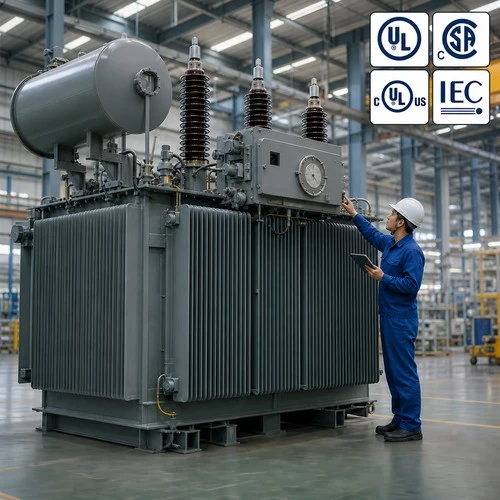
Ryan Electric has built distribution and power transformers since 2007 in our 120,000 m² facility, and tap changer specification is a daily conversation, not an occasional one. As an Eaton joint venture partner with UL, CSA, IEEE, and DEKRA certifications in our portfolio, we design with both markets in mind: pad-mounted units for North America ship with the DETC positions and ratio test data your utility standard expects, while substation units for weak-grid regions ship with motorized OLTCs, control wiring diagrams, and the full per-tap test record.
Our engineers will tell you the same thing in every call: tell us the voltage you receive, the voltage you need, and the load shape in between. From those three numbers we can recommend the tap changer type, the range, and the positions - usually within one working day.

Not Sure Which Tap Changer Your Project Needs?
Send us your incoming voltage data, required output voltage, and transformer rating through ryan-transformers.com, and our engineering team will come back with a tap changer recommendation, the range calculation, and a realistic schedule. The transformer tap changer decision is one of the few spec items you can get right in a single email - and wrong on a $50,000 transformer costs far more than the email.
About the Author: This article was written by the engineering team at Ryan Electric, an Eaton joint venture partner and UL/CSA-certified transformer manufacturer in Jiangsu, China, serving utility, industrial, and EPC clients across North America, Southeast Asia, the Middle East, and Africa.