

Two summers ago a food-processing plant in the Midwest called us about a 750 kVA dry type transformer that kept tripping its over-temperature relay. The plant manager was frustrated because the panel ammeter showed 62% of nameplate load - the unit looked half idle. When one of our engineers ran a power-quality survey, the picture changed: variable-frequency drives feeding six extruders were pulling distorted current with roughly 34% total harmonic distortion, and the winding hot spot was climbing past 150 °C on summer afternoons. The transformer was not oversized. It was quietly under-rated for the current actually flowing through it.

Why Harmonic Currents Overheat a Transformer
A transformer nameplate is calculated on the assumption of clean 60 Hz sinusoidal current. Non-linear loads - VFDs, UPS systems, LED drivers, EV chargers, and rectifier front ends - draw current in short pulses rather than smooth sine waves. That distorted waveform is a stack of sine waves at multiples of the fundamental frequency: the 5th (300 Hz), 7th (420 Hz), 11th, and 13th orders usually dominate.
The damage shows up in winding losses. Load loss in a transformer has two parts: the I²R loss that scales with RMS current, and eddy-current loss that scales with frequency. Eddy loss in the windings grows roughly with the square of the harmonic order - a 5th harmonic at 30% of fundamental magnitude raises that component of eddy loss by a factor of (0.30 × 5)² ≈ 2.3. Skin and proximity effects push the extra current into small conductor regions, which is why a distorted load creates local hot spots that an ammeter never reveals. Here is the part most buyers miss: total harmonic distortion can look modest and still cook a winding, because the 5th and 7th orders sit exactly where the loss penalty is highest.
For the distortion limits themselves, IEEE 519-2022 is the reference engineers use to judge how much harmonic current an electrical system should tolerate at the point of common coupling. It sets current limits by harmonic order and by the system's short-circuit ratio - and it is the document your harmonic study should be measured against before you buy a transformer, not after.
What a K-Factor Transformer Rating Actually Means
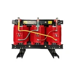
A K-factor transformer is not a different machine from a standard dry type unit - it is the same transformer family with windings designed to shed the extra eddy heat created by harmonic currents. The K rating, recognized by UL under UL 1561 and computed with the method in IEEE C57.110, weights each harmonic current in the load by the square of its order and expresses the result as a single number: K-1 for a plain linear-load design, then K-4, K-9, K-13, K-20, K-30, K-40, and K-50.
K-13 is the rating we quote most often in industrial plants, because supplier guidance commonly treats it as suitable where the non-linear share of the load approaches 75%. K-4 covers general commercial floors with lighting and small UPS units. K-20 and above belong to heavy converter duty - large UPS concentrations, arc furnaces, and electrochemical rectifier loads - and should be confirmed with a spectrum-based calculation rather than a guess. As a starting point, here is the mapping we walk buyers through:
| Typical Load Profile | Suggested K Rating |
| General office: lighting, PCs, small UPS | K-4 |
| Commercial: elevators, VFD pumps, UPS rooms | K-13 |
| Industrial: drive-heavy MCCs, extruders, compressors | K-13 |
| Data center: high-density switching, large UPS | K-13 to K-20 |
| Severe: arc furnaces, electrolytic rectifiers | K-30 to K-50 |
The K number is not a derating instruction - it is a design target for the winding. A standard transformer forced to feed the same load either runs hotter than its temperature-rise class allows or must be derated below nameplate, and derating a standard unit is sometimes the cheaper answer. Both paths are legitimate. The mistake is picking either one without looking at the load spectrum first.
IEEE C57.110: The Method Behind the Rating
IEEE C57.110-2018 - the Recommended Practice for Establishing Liquid-Immersed and Dry-Type Power and Distribution Transformer Capability when Supplying Nonsinusoidal Load Currents - is the calculation behind the label. The current edition is available from the IEEE Standards Store. The method defines a harmonic loss factor, usually written FHL, that compares total winding eddy loss under your measured spectrum with eddy loss at rated sinusoidal current, then turns that factor into an allowable current: either the maximum kVA a standard unit can carry for your spectrum, or the K design a new unit needs.
Using the method requires one piece of data that only the manufacturer has: the eddy-current loss of the winding expressed as a percentage of its I²R loss. That is why a serious quote for a harmonic-heavy project should include the transformer's % eddy loss figure and a computed FHL for your load - not just a K number on a datasheet. When a customer sends us a harmonic study with their RFQ, we return the calculation both ways, as a K-rated design and as a derated standard design, so the comparison is built on real numbers.
One caveat from the field: nameplate K ratings are assigned at a defined spectrum, and real plants drift. If you add drives later, re-run the survey. We have replaced units that were correctly rated K-9 at commissioning and outgrown five years later when a second production line came online.
Where We See It Fail in the Field
Back to that food-processing plant. The survey showed 34% total current distortion, dominated by the 5th and 7th harmonics from the extruder drives, and the computed eddy-loss penalty put the unit's real capacity near 70% of nameplate - which matched the nuisance trips almost exactly. We replaced the 750 kVA standard unit with a K-13 dry type transformer of the same rating, and the temperature alarms stopped. The load had not changed. The winding was finally built for the current it was actually carrying.

The second pattern is quieter. A packaging plant in Mexico asked us to quote a K-13 unit, then asked why they could not simply buy a standard unit and derate it by 30%. They could - and for their duty, derating plus an active harmonic filter on the worst feeder was measurably cheaper. The point is not that K-rated transformers are always the answer. The point is that nobody should decide without the spectrum and the loss calculation, because both the K design and the derating path depend on numbers, not opinions.
How to Spec a K-Factor Transformer: RFQ Checklist
If you are buying a dry type unit for a plant or building with drives, UPS systems, or chargers, the specification work happens before the RFQ goes out. Five items cover most of it:
- Run or request the harmonic study first. Measure current distortion at the transformer bus per IEEE 519-2022 and record the TDD plus the dominant orders - usually the 5th, 7th, 11th, and 13th.
- Let the supplier compute the K from your spectrum. Send the study with the RFQ. A K picked because another plant used it is a guess dressed as engineering.
- Compare K-rated against derated standard on total cost. Purchase price, footprint, losses, and the filter you may need either way all belong in the comparison.
- Confirm the certification matches the design. For North America, ask whether the K-rated unit carries a UL listing under UL 1561 - or the CSA certification - for the exact design, not just for the product family.
- Ask for the temperature-rise class and the FHL calculation in the test package. Then your engineer can verify the rating instead of trusting a nameplate.
And keep the door open to filtering. If the dominant load is one large VFD cluster, an active filter in front of a standard transformer can beat a K-30 unit on price. We quote the comparison either way - that honesty is cheaper than the wrong transformer.
Ryan Electric's Take
Ryan Electric has built dry type and liquid-immersed transformers in our 120,000 m² facility in Jiangsu since 2007, and K-factor transformer builds - cast resin and VPI - are a standard part of the range. As an Eaton joint venture partner with UL, CSA, IEEE, and DEKRA certifications in our portfolio, we treat the K question as a calculation. Send us your load profile and we will run the C57.110 loss numbers before you commit to a design.
If you are specifying dry type transformers for a facility with VFDs, UPS rooms, EV chargers, or any other non-linear load, share your kVA, voltage class, and harmonic data through ryan-transformers.com - our engineers will come back with the K recommendation, the loss calculation, and a realistic schedule. Or, if the data says a standard unit plus a filter is the smarter buy, we will tell you that too.
About the Author: This article was written by the engineering team at Ryan Electric, an Eaton joint venture partner and UL/CSA-certified transformer manufacturer in Jiangsu, China, serving industrial, commercial, and utility clients across North America, Latin America, Southeast Asia, and the Middle East.