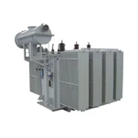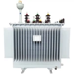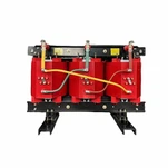


When a high-voltage substation transformer trips on energization or during an external through-fault, the immediate suspicion often falls on internal winding failure. Yet, in over 70% of field nuisance trip investigations, the transformer itself is in pristine condition. The true culprit is almost always misconfigured protective relay logic-specifically uncoordinated percentage slopes, improper harmonic filtering thresholds, or asymmetrical current transformer (CT) saturation. Implementing reliable transformer differential protection requires a rigorous engineering approach that balances high-speed tripping for internal short circuits with rock-solid stability during severe external fault transients and magnetizing inrush events.
Modern numerical relays make 87T relay coordination exceptionally versatile, allowing software-driven phase correction, zero-sequence filtering, and adaptive restraint curves. However, digital flexibility cannot compensate for incorrect fundamental settings. Whether you are engineering a 5 MVA industrial substation or a 50 MVA utility step-down unit, this engineering guide details the mathematical principles, slope configurations, harmonic restraint mechanisms, and CT sizing rules necessary to achieve dependable unit protection.
Fundamentals of Percentage Differential Protection (87T)
The primary principle governing transformer differential protection is Kirchhoff's Current Law: the total current entering a defined electrical zone must equal the total current exiting that zone under normal operating conditions. Differential relays measure currents on the primary and secondary (and tertiary, if applicable) sides of the transformer through dedicated current transformers. The relay calculates two fundamental quantities on a per-phase basis: operating (differential) current and restraint current.
The operating differential current (Idiff) represents the phasor sum of all normalized terminal currents entering the transformer zone:
Idiff = |Iprimary + Isecondary|
Under ideal conditions with no internal faults, Iprimary and Isecondary are equal in magnitude and 180 degrees out of phase, resulting in Idiff = 0. In practice, small mismatch currents inevitably exist due to CT transformation errors, magnetizing excitation current, and on-load tap changer (OLTC) voltage adjustments. To prevent these spurious currents from causing an unwanted trip, relays utilize a restraint current (Irestraint), typically defined as the average or maximum of the terminal current magnitudes:
Irestraint = (|Iprimary| + |Isecondary|) / 2
The relay compares Idiff against Irestraint using a percentage differential characteristic. The unit issues a trip command only when the operating current exceeds a predefined percentage of the restraint current, ensuring high security during normal full-load throughput.
Sizing the Dual-Slope Differential Characteristic
1. Minimum Pickup Setting (Ipickup)
The minimum pickup current establishes the base sensitivity of the differential element under low-load conditions. It must be set above the transformer's steady-state core excitation current (typically 0.5% to 1.5% of rated current) and the cumulative steady-state CT ratio mismatch errors. Industry best practice per IEEE standard guidelines for power transformer protection (IEEE C37.91) recommends setting Ipickup between 0.20 pu and 0.35 pu (per unit of transformer rated current).
2. Slope 1 Selection (Normal Operating Region)
Slope 1 governs relay sensitivity between Ipickup and the knee-point breakpoint (typically up to 1.5 to 2.5 pu load current). In this region, false differential current arises primarily from three sources: on-load tap changer (OLTC) position variation (typically ±10% to ±15% voltage shift), steady-state CT ratio errors (±2.5% to ±5%), and relay measurement tolerances. A standard Slope 1 setting ranges from 25% to 35%. Setting Slope 1 below 20% risks nuisance tripping when the transformer operates at maximum buck or boost tap positions.
3. Knee-Point Breakpoint and Slope 2 (Through-Fault Region)
When an external short circuit occurs outside the differential zone, through-fault currents can reach 10 to 20 times the transformer rated current. Under such extreme current magnitudes, unequal magnetic saturation among the primary and secondary CTs generates massive false differential currents. To prevent false trips during external faults, the relay transitions into Slope 2 at the breakpoint (IBP ≈ 2.0 to 3.0 pu). Slope 2 is configured with a steep restraint slope-typically between 50% and 80%-ensuring total stability even when one set of CTs experiences severe saturation.
Harmonic Inrush Restraint and Overexcitation Mitigation
Energizing an unloaded power transformer produces a severe magnetizing inrush current that flows into the primary winding without exiting the secondary winding. To the differential relay, this inrush appears indistinguishable from an internal short circuit. Traditional overcurrent elements would trip instantaneously. To overcome this, numerical relays rely on advanced harmonic inrush restraint and harmonic blocking algorithms.
Magnetizing inrush current waveforms are characterized by high asymmetry, unidirectional DC offset, and a dominant second harmonic (100 Hz on 50 Hz systems; 120 Hz on 60 Hz systems) content. Mathematical and physical testing demonstrates that inrush waveforms consistently contain between 15% and 60% second harmonic relative to the fundamental frequency current. Modern relays calculate the ratio of the second harmonic component (I2nd) to the fundamental component (I1st):
Second Harmonic Ratio = (I2nd / I1st) × 100%
The second harmonic threshold is typically configured between 15% and 20%. When modern high-grade silicon steel cores (such as domain-refined grain-oriented electrical steel) are used, lower inrush harmonic content can occur. For modern low-loss cores, setting the second harmonic restraint threshold at 15% or utilizing cross-phase harmonic averaging prevents false trips during cold-load pickups.
In addition to inrush, power transformers are susceptible to overexcitation caused by sustained system overvoltage or low system frequency (elevated Volts/Hertz). Overexcitation drives the transformer core deep into magnetic saturation, creating odd harmonics-predominantly the fifth harmonic (250 Hz / 300 Hz). The relay incorporates fifth harmonic restraint, typically set between 25% and 35%, preventing the unit from tripping on temporary transmission overvoltages while allowing Volts/Hz protection (ANSI 24) to execute controlled clearing if cooling limits are breached.

Phase Shift Compensation and Zero-Sequence Elimination
Most medium and high-voltage power transformers utilize Delta-Wye (Δ-Y) or Wye-Delta (Y-Δ) vector group configurations (such as Dyn1, Dyn11, or YNd11). These winding connections introduce an inherent 30-degree electrical phase angle displacement between primary and secondary line currents. In legacy electromechanical schemes, auxiliary interposing CTs connected in Wye on the Delta side and Delta on the Wye side were required to manually cancel the phase shift.
In contemporary digital relays, all phase shift compensation is computed internally via software matrix transformations. Protection engineers configure the transformer vector group, and the relay automatically realigns the primary and secondary current phasors before executing differential calculations.
Equally vital is zero-sequence current elimination. On grounded-Wye windings, an external ground fault on the downstream network causes zero-sequence current (3I0) to circulate through the neutral bushing. If the delta winding does not allow zero-sequence current to pass through to the primary grid, a severe false differential current will appear in the relay. Digital relays eliminate this hazard by mathematically subtracting the zero-sequence component from the Wye-side phase currents (software Delta filtering), ensuring absolute security for out-of-zone ground faults.
CT Selection and Saturation Mitigation
Proper current transformer specification is the foundation of dependable transformer differential protection. Even the most sophisticated numerical relay algorithm cannot function correctly if CT secondary outputs are completely distorted by core saturation during an internal or through-fault event. Implementing robust CT saturation mitigation requires verifying CT accuracy class and total secondary circuit burden.
In North American applications governed by IEEE C57.13, protection engineers specify Class C bushing current transformers (BCTs), such as C400 or C800. The C-rating defines the secondary terminal voltage the CT can deliver at 20 times rated current without exceeding 10% ratio correction error. The minimum required knee-point voltage (Vk) must satisfy the classic saturation equation:
Vk ≥ Ifault_max × (Rct + 2 × Rlead + Rrelay) × (1 + X/R)
Where Ifault_max is the maximum symmetrical secondary through-fault current, Rct is the CT internal winding resistance, Rlead is the one-way cable resistance, Rrelay is the relay input impedance, and X/R is the system primary time constant ratio. Accounting for the DC offset factor (1 + X/R) ensures that the CT core will not saturate during the critical first few cycles of an asymmetrical short circuit.
Engineering Field Insight: Troubleshooting a Commissioning Nuisance Trip
During the field commissioning of a 20 MVA, 34.5 kV to 4.16 kV Dyn11 step-down transformer at a heavy industrial manufacturing facility, the primary vacuum breaker tripped on 87T instantaneous differential during initial no-load energization. The initial test logs showed a differential current of 3.8 pu on Phase B, causing immediate concern regarding internal coil damage.
Our engineering team performed a detailed COMTRADE waveform event record analysis from the digital relay. The oscillography revealed that residual magnetic core flux from previous factory DC resistance testing had created a highly asymmetrical inrush current. While Phase A and Phase C exhibited healthy 2nd harmonic ratios of 22% and 26%, Phase B's 2nd harmonic dipped to 11.4%-just below the relay's individual-phase harmonic blocking threshold of 15%.
By enabling cross-phase harmonic averaging (where the presence of >15% second harmonic on any single phase restrains differential tripping across all three phases for the first 10 cycles), and verifying that the high-set unrestrained differential element (87U) was set comfortably above peak inrush at 10.0 pu, the unit was successfully re-energized with zero nuisance trips. This real-world experience demonstrates why protection engineers must look beyond single-phase threshold numbers during commissioning.
Ryan Electric: Precision Manufacturing and Relay Integration
At Ryan Electric, reliable transformer protection begins at the design stage. Operating from our 120,000 square meter state-of-the-art manufacturing facility equipped with over 180 advanced production machines and backed by 37 technical patents, we engineer substation, pad-mounted, and dry-type transformers with fully integrated protection solutions. Drawing upon our official joint venture partnership with Eaton since 2023, Ryan Electric combines tier-one global power engineering standards with exceptional manufacturing agility.
All Ryan Electric substation and power transformers are available with factory-integrated multi-ratio Bushing Current Transformers (BCTs) certified to ANSI/IEEE C57.13 and IEC 61869-2 standards. We provide complete factory excitation curves, winding resistance measurements, and pre-calculated CT burden sheets with every unit, ensuring seamless integration into your facility's 87T relay coordination scheme. Certified across UL, CSA, IEEE, DEKRA, and CE frameworks, our transformers deliver uncompromising performance in the most demanding utility, data center, and industrial applications.
Conclusion and Engineering Action Plan
A successful transformer differential protection scheme requires precise coordination between transformer physical design, CT performance characteristics, and numerical relay settings. By correctly implementing dual-slope percentage curves, harmonic inrush restraint thresholds, and software-based vector group compensation, engineering teams can guarantee ultra-fast internal fault isolation while eliminating costly false trips.
Are you planning a new substation installation or upgrading protective relay settings on your existing medium-voltage transformers? Contact the Ryan Electric engineering team today for technical consultations, customized BCT sizing analyses, and certified transformer quotation packages tailored to your project requirements.
About the Author
Senior Substation Protection & Application Engineering Team at Ryan Electric. With extensive field commissioning experience across North American utility networks, heavy industrial facilities, and renewable energy substations, our engineers specialize in power transformer design, protection relay coordination, and grid code compliance.