

1. Thermal Dynamics: Sizing for Continuous 100% Capacity Factor Without Insulation Degradation
Direct Air Capture (DAC) and Point-Source Carbon Capture, Utilization, and Storage (CCUS) facilities represent one of the most demanding power engineering challenges in modern industrial decarbonization. While conventional commercial and utility distribution transformers are engineered around cyclic load curves with typical average utilization rates between 50% and 60%, a carbon capture facility transformer operates in a completely different operating envelope. These facilities run non-stop, 24 hours a day, 365 days a year, at continuous 95% to 100% capacity factors to power multi-megawatt CO2 compression trains, giant air contactor fan arrays, solvent regeneration pumps, and thermal desorption units.
When project developers and EPC contractors specify standard distribution units for large-scale carbon capture infrastructure, they frequently encounter severe early-stage reliability bottlenecks: premature winding insulation degradation from sustained thermal hotspots, harmonic overheating from medium-voltage variable frequency drives (VFDs), and aggressive tank corrosion caused by coastal salt fog combined with chemical amine wash aerosols. Selecting and sizing the right compressor duty transformer requires a deep technical understanding of continuous thermal aging kinetics, non-sinusoidal harmonic mitigation, and severe-duty environmental enclosure engineering.
In a standard commercial substation, transformers benefit from natural diurnal load shedding, allowing internal winding and oil temperatures to cool down during off-peak nighttime hours. In sharp contrast, a carbon capture plant operates as a continuous baseload industrial process. When several 5,000 HP (3.7 MW) or 10,000 HP (7.5 MW) centrifugal CO2 compressors run concurrently under peak summer ambient conditions-such as 45°C (113°F) in the Texas Permian Basin or the Gulf Coast-the transformer winding temperature never experiences a cooling cycle.
Under these conditions, standard 65°C average winding temperature rise designs rapidly push the internal winding hottest-spot temperature past the critical 110°C threshold established in IEEE standards. According to the IEEE C57.91 Loading Guide for Mineral-Oil-Immersed Transformers, transformer insulation thermal aging rate (Aging Acceleration Factor, FAA) doubles for roughly every 6°C to 7°C increase in hottest-spot temperature above normal design limits. A continuous hotspot temperature of 120°C reduces standard cellulose insulation life by a factor of four, turning a nominal 30-year design life into an unacceptable 7-year asset replacement liability.
To guarantee a 30-year operational lifespan under non-stop full load, engineering teams must specify a conservative 55°C average winding rise rating (or dual 55/65°C rating with supplementary ONAN/ONAF cooling). Furthermore, upgrading from standard kraft paper to thermally upgraded insulation (thermal Class 120°C) or synthetic Nomex aramid paper, paired with ester dielectric fluids like FR3 (which feature a fire point >300°C and superior moisture-scavenging properties), maintains the thermal aging factor FAA ≤ 1.0 even during sustained maximum plant throughput.
2. Mitigating High Harmonic Heating from Multi-Megawatt Compressor VFDs
Large gas compressors in carbon capture plants rely extensively on medium-voltage variable frequency drives (VFDs) and adjustable speed drives (ASDs) to maintain precise suction pressures and process flow control across fluctuating atmospheric capture rates. While multi-pulse (12-pulse, 18-pulse, or 24-pulse) and Active Front End (AFE) inverter topologies significantly reduce grid-side current total harmonic distortion (THD), the transformer secondary windings still carry substantial non-sinusoidal harmonic currents, notably the 11th, 13th, 23rd, and 25th orders.
These high-frequency harmonic currents induce two major parasitic loss mechanisms inside the transformer: winding eddy current losses (P_EC) and structural stray losses (P_OS) in the core clamps, tie plates, and tank walls. In a standard transformer, winding eddy losses scale with the square of the harmonic frequency (f²), causing intense localized overheating that standard thermal imaging cameras cannot detect from the exterior tank surface.
Specifying a high-reliability high harmonic VFD transformer for carbon capture compressor duty requires specific internal electromagnetic design provisions:
• Continuously Transposed Conductors (CTC): Utilizing CTC or multi-strand transposed copper strips rather than solid rectangular conductors drastically reduces skin effect and proximity-effect eddy current losses across high harmonic frequencies.
• Conservative K-Factor Rating: Sizing windings for a minimum K-13 (for 18-pulse/24-pulse VFDs) or K-20 (for 6-pulse/12-pulse heavy drive loads) ensures adequate cross-sectional copper area and reduced current density (typically < 2.5 A/mm²).
• Electrostatic Ground Shields: Grounded copper electrostatic shielding placed between primary and secondary windings suppresses high-frequency common-mode noise and prevents drive-generated transient voltage spikes (dV/dt) from coupling into the primary distribution grid.
3. Environmental Protection: Engineered for Severe Chemical and Marine Atmospheres
Carbon capture plants combine chemical solvent processing with massive air-intake contactors that ingest millions of cubic feet of ambient air per hour. The local microclimate around absorber columns, direct contact coolers, and stripping towers contains aerosolized moisture, trace amine vapors (such as MEA and piperazine degradation byproducts), acidic CO2 condensate, and high ambient humidity. In coastal or industrial estuary installations, this chemical cocktail is further exacerbated by heavy airborne sodium chloride deposits.
Standard commercial powder-coat or alkyd paint systems blister, micro-crack, and delaminate within 24 to 36 months under these conditions, exposing the carbon steel tank and radiator fins to severe pitting corrosion. To ensure true long-term survivability, a corrosion resistant substation transformer must comply with strict industrial coating standards:
All structural steel tanks, radiator assemblies, and base frames must be specified and certified in accordance with ISO 12944-5 Category C5-M / CX Severe Industrial and Marine Environments. This multi-stage coating system incorporates a surface blast to ISO 8501-1 Sa 2.5, a zinc-rich epoxy primer (minimum 75 µm), a high-build polyamide epoxy intermediate barrier coat (150 µm), and an aliphatic polyurethane topcoat (minimum 75 µm), delivering a total dry film thickness (DFT) exceeding 320 µm. Radiator banks must be hot-dip galvanized prior to paint application or fabricated from 316L stainless steel for maximum atmospheric resilience.
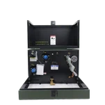
Furthermore, low-voltage control cabinets, marshalling boxes, and pressure relief device (PRD) housings must be constructed from NEMA 4X / IP66 marine-grade 316L stainless steel with continuous seam welds, silicone perimeter gaskets, and internal condensation heaters.
4. Technical Comparison: Standard Industrial vs. Carbon Capture Severe-Duty Transformers
The table below outlines the critical design and specification differences between a conventional industrial distribution unit and a dedicated severe-duty transformer engineered for CCUS and direct air capture plants:
| Specification Parameter | Standard Industrial Transformer | Ryan CCUS / DAC Severe-Duty Unit |
|---|---|---|
| Operating Duty Cycle | Cyclic / Intermittent (50-60% avg load) | 24/7 Continuous Full-Load (95-100% capacity factor) |
| Average Winding Rise | 65°C standard rise | 55°C low-rise (or dual 55/65°C with 115% fan rating) |
| Hotspot Allowance (HSR) | Up to 118°C (high aging rate) | Limited to ≤ 95°C at 100% continuous nameplate rating |
| Harmonic Capacity | K-1 standard (sinusoidal) | K-13 to K-20 rated with CTC transposed copper windings |
| Dielectric Insulation Fluid | Standard Mineral Oil (Class I) | High-Fire-Point Natural Ester (FR3) or Synthetic Ester |
| Tank & Radiator Coating | Standard C2/C3 Alkyd Paint (<120 µm) | ISO 12944 C5-M / CX Multi-Coat System (DFT ≥ 320 µm) |
| Control & Terminal Enclosure | NEMA 3R Painted Carbon Steel | NEMA 4X / IP66 Seamless 316L Stainless Steel |
5. Ryan Electric Manufacturing Capabilities and Engineering Backing
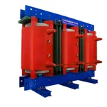
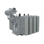
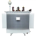
Engineering custom power equipment for mission-critical industrial decarbonization requires deep manufacturing discipline and rigorous quality control. At Ryan Electric, our 120,000 m² state-of-the-art manufacturing facility operates more than 180 advanced production machines and holds 37 proprietary transformer engineering patents. We design, manufacture, and test comprehensive lines of liquid-filled substation transformers, pad-mounted units, and cast resin dry-type transformers rated from 10 kV up to 200 MVA.
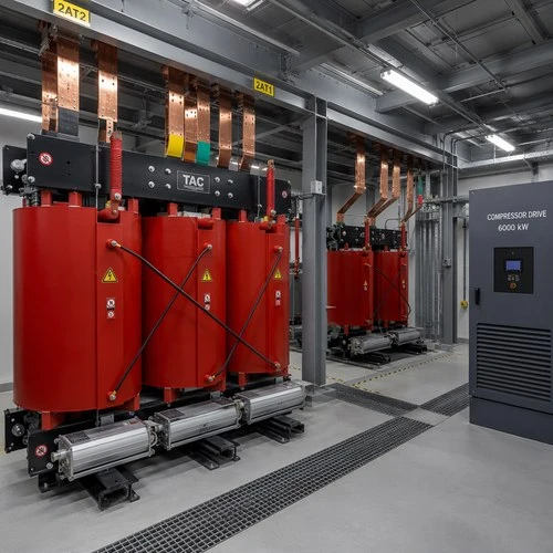
Every unit is fully certified under rigorous international standards, including UL, cULus, CSA, IEEE, DEKRA, and CE mark accreditations. In our ongoing engineering synergy with Eaton since 2023, Ryan integrates tier-one electromagnetic finite element analysis (FEA), automated robotic foil winding, and precision vacuum pressure impregnation (VPI) to deliver custom transformers with industry-leading low-loss performance and robust short-circuit withstand capabilities. Whether deploying indoor cast resin isolation units for high-power inverter rooms or massive 34.5 kV substation step-up transformers for regional capture hubs, Ryan provides engineered solutions tailored to exact project specifications.
6. Field Case Study: Powering a 500,000-Ton/Year Direct Air Capture Facility
During the commissioning of a large-scale 500,000-ton/year commercial direct air capture facility in west Texas, the project EPC faced a severe dilemma: the site's main electric compressor substation was located less than 50 meters from the solvent washing column downwind, where ambient summer temperatures peaked at 46°C with constant exposure to amine chemical aerosols.
Ryan Electric engineered and delivered three custom 15 MVA, 34.5 kV to 4.16 kV outdoor substation transformers equipped with ONAN/ONAF cooling stages, 55°C winding temperature rise ratings, K-13 harmonic shielding, and full ISO 12944 C5-M marine-grade exterior coating. During continuous full-capacity trials throughout July and August heatwaves, comprehensive online fiber-optic temperature sensors confirmed that the top-oil temperature never exceeded 81.5°C, and winding hotspot temperatures remained comfortably below 93°C-well within our guaranteed limits.
7. Engineering Specification Checklist for Carbon Capture Project Developers
Before finalizing your balance-of-plant (BOP) transformer procurement packages for carbon capture or DAC facilities, ensure your engineering datasheets incorporate the following four non-negotiable clauses:
1. Specify 55°C average winding rise (or dual 55/65°C) to ensure an IEEE C57.91 thermal aging acceleration factor FAA ≤ 1.0 under 24/7 continuous 100% nameplate loading.
2. Require K-13 or K-20 harmonic rating calculations based on actual VFD manufacturer harmonic spectra, including transposed CTC winding construction and electrostatic shielding.
3. Mandate ISO 12944 C5-M / CX heavy-duty coating with minimum 320 µm DFT on all external tanks and hot-dip galvanized radiators to resist amine aerosol and coastal salt corrosion.
4. Demand complete factory acceptance test (FAT) reports verifying temperature rise under rated harmonic current and full dielectric lightning impulse (BIL) withstand tests.
Are you planning a new carbon capture, direct air capture, or industrial decarbonization electrification project? Contact the engineering team at Ryan Electric today to discuss custom transformer sizing, lead-time optimization, and technical specifications for your facility.
About the Author
David Vance is a Senior Applications Engineer at Ryan Electric specializing in heavy industrial substation design, harmonic mitigation for large motor drives, and severe-environment transformer applications across North America and global energy markets.