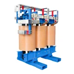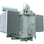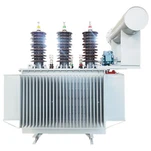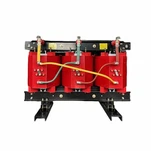


As commercial green hydrogen production scales from megawatt-scale demonstration projects to gigawatt-class industrial hubs, the electrical balance of plant (eBoP) has emerged as the decisive factor governing overall plant efficiency and Levelized Cost of Hydrogen (LCOH). At the heart of every power-to-gas facility sits the heavy-duty rectifier transformer for green hydrogen. Whether supplying proton exchange membrane (PEM) stacks or pressurized alkaline water electrolyzers, this specialized converter transformer must step down medium-voltage grid or renewable power (13.8 kV to 34.5 kV) into high-current, low-voltage AC feeds (typically 200 V to 1,000 V at 5,000 A to 35,000 A) that feed thyristor or IGBT rectifier skids.
Unlike standard utility distribution transformers that operate under sinusoidal linear loads, an electrolyzer power supply transformer experiences relentless non-linear current distortion, severe stray flux heating, and extreme dynamic cyclic loading tied to solar and wind generation profiles. According to authoritative research on Hydrogen Production: Electrolysis by the U.S. Department of Energy (DOE), electrical power conversion losses directly degrade the net system efficiency of green hydrogen systems. Specifying a rugged, highly efficient rectifier transformer for green hydrogen demands a comprehensive understanding of multi-pulse winding topologies, harmonic cancellation physics, stray loss containment, and low-voltage busbar thermal management.
The Electrochemical Load Profile: Why Standard Transformers Fail in Electrolysis Service
Water electrolysis is fundamentally a high-current, low-voltage DC electrochemical process. Modern industrial alkaline electrolyzers operate at cell voltages between 1.8 V and 2.2 V DC with stack currents frequently exceeding 10,000 A, while PEM stacks operate with higher current densities and rapid dynamic response requirements. Delivering hundreds of megawatts of DC power creates a punishing operational environment for step-down transformers.
When a standard distribution transformer is subjected to rectifier duty, the non-sinusoidal currents drawn by semiconductor bridge circuits generate severe harmonic frequencies (predominantly 5th, 7th, 11th, and 13th orders in 6-pulse systems). These harmonics dramatically increase winding eddy current losses (proportional to the square of the frequency, P_EC ∝ I^2 · f^2) and structural stray losses in the core clamps, tank walls, and tie plates. Without proper derating and electromagnetic shielding, standard units rapidly suffer localized hotspot overheating, dielectric oil degradation, and premature insulation breakdown.
Furthermore, utility interconnect agreements enforce strict power quality limits under IEEE 519-2022. Direct 6-pulse rectification injects up to 30% Total Harmonic Current Distortion (THD_i) back into the medium-voltage collector grid, necessitating massive external harmonic filters. The industry solution is to integrate harmonic cancellation in rectifier transformers through multi-pulse phase-shifting topologies.
Multi-Pulse Topologies: 12-Pulse vs. 24-Pulse Rectification Architectures
The primary method for eliminating low-order harmonics at the transformer level is phase-shifting multiple secondary windings. By shifting the phase angle between secondary feeds supplying parallel 6-pulse bridge rectifiers, harmonic current vectors cancel each other out in the primary winding and upstream utility network.
In a 12-pulse multi-pulse rectifier transformer, the primary winding feeds two separate secondary windings: one connected in Delta (0° phase shift) and one in Wye (-30° phase shift), or a pair of zig-zag extended delta windings providing a net 30° displacement. This 30° phase shift causes the 5th and 7th harmonic currents to be 180° out of phase, theoretically eliminating them from the primary line current. In a 24-pulse configuration, four secondary windings with a 15° relative phase shift (e.g., +22.5°, +7.5°, -7.5°, -22.5°) cancel the 5th, 7th, 11th, 13th, 17th, and 19th harmonics, driving the primary current Total Demand Distortion (TDD) below 4% without requiring active harmonic filters.
| Rectifier Topology | Secondary Winding Configuration | Dominant Harmonics Cancelled | Input Current THD-i |
|---|---|---|---|
| 6-Pulse (Standard Bridge) | Single Secondary (Delta or Wye) | None (5th, 7th, 11th present) | 28% – 35% |
| 12-Pulse (Dual Secondary) | Dual Secondary (Delta / Wye, 30° shift) | 5th, 7th harmonics cancelled | 8.5% – 12.0% |
| 24-Pulse (Quad Secondary) | Quad Secondary (Extended Delta / Zigzag, 15° shift) | 5th, 7th, 11th, 13th, 17th, 19th cancelled | 2.5% – 4.0% |
| Active Front End (AFE) / IGBT | Single or Dual Multi-Winding Low Inductance | High frequency switching attenuation | < 3.0% (Unity Power Factor) |
Electromagnetic and Thermal Engineering for Heavy Secondary Currents
Designing an electrolyzer power supply transformer for 10 MW to 50 MW electrolyzer blocks requires extreme attention to low-voltage conductor design and structural stray flux management. When secondary winding currents reach 15,000 A to 30,000 A per phase, the magnetic leakage field in the window space and tank periphery becomes intense.
To prevent catastrophic hotspot temperatures, Ryan Electric implements three core engineering principles in compliance with IEEE C57.18.10 and IEC 61378-1 converter transformer standards:
1. Continuously Transposed Conductors (CTC) with Epoxy Bonding: Standard rectangular copper conductors suffer massive skin effect and proximity effect losses at harmonic frequencies. CTC windings composed of dozens of individually enameled copper strands continuously transposed along the coil length equalize current distribution and reduce winding eddy losses by up to 60%.
2. Non-Magnetic Stainless Steel Tank Inserts and Magnetic Shunting: Heavy-current low-voltage bushing turrets are equipped with non-magnetic 304/316L stainless steel entry plates to eliminate closed eddy current loops around phase conductors. High-permeability silicon steel magnetic shunts and aluminum shielding plates line the interior tank walls to channel stray flux away from structural steel members.
3. Interphase Reactor (IPR) Integration: In multi-secondary 12-pulse systems operating with interphase reactors, ensuring equal current sharing between bridge rectifiers is vital. Ryan incorporates precision-tuned interphase reactors with high linearity across the full 0% to 120% load range to prevent DC saturation and unbalanced rectifier arm commutation.
Field Experience: Overcoming Thermal Expansion in a 20 MW Desert Green Ammonia Facility
When our engineering team designed and manufactured a batch of 15 MVA 33 kV to 2x690 V multi-pulse rectifier transformer units for a desert green ammonia plant in the Middle East, ambient temperatures routinely reached 52°C with intense solar radiation. The electrolyzers operated on dynamic solar PV power, swinging from 15% minimum turndown at dawn to 110% peak capacity at solar noon within 45 minutes.
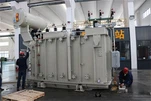
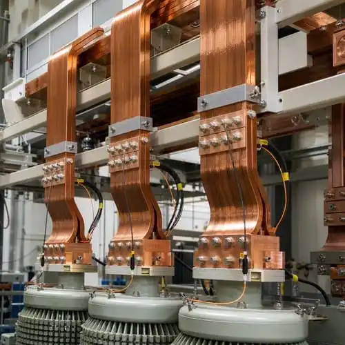
During initial full-load heat run testing in our test hall, standard rigid copper busbar terminations exhibited localized thermal expansion stresses that risked compromising the bushing gasket seals. Our engineers redesigned the secondary terminations with laminated flexible copper expansion braids and installed direct fiber-optic temperature sensors embedded inside the innermost winding layers. Furthermore, we engineered the cooling system with high-fire-point synthetic ester dielectric fluid (K-class, fire point > 300°C) and forced-directed oil-forced air (ODAF) radiators. On site, the transformers operate continuously with top-oil temperature rises maintained below 48K, ensuring uninterrupted hydrogen production even during peak summer heat.
Specifying Green Hydrogen Transformers: Procurement Checklist and Standards Compliance
Procurement teams and electrical engineering consultants should never order hydrogen rectifier transformers using generic distribution transformer data sheets. To ensure asset reliability and grid compliance, include these critical specifications in your tender documents:
• Applicable Standards: Demand dual compliance with IEEE C57.18.10 (Semiconductor Power Rectifier Transformers) and IEC 61378-1 (Converter Transformers for Industrial Applications).
• Harmonic Current Spectrum Definition: Provide the full harmonic magnitude spectrum (from fundamental up to 49th harmonic) from the rectifier OEM, along with the expected K-factor (typically K-13 to K-20) and Total Harmonic Distortion.
• Impedance Matching and Tolerance: For multi-secondary transformers, specify tight impedance matching tolerances (typically within ±2.5% between secondary windings) to guarantee balanced current sharing between rectifier bridges.
• Thermal Class and Dielectric Fluid: For indoor or containerized electrolyzer rooms, specify Cast Resin dry-type or Natural/Synthetic Ester (FR3/Midel) to satisfy NFPA 70 / NEC 450 fire separation clearances.
• Dynamic Cycling Capability: Specify the cyclic duty curve and rate of change of power (MW/min) to ensure mechanical winding clamping structures can withstand thermal cycling stresses from renewable energy intermittency.
As explored in the U.S. Department of Energy Hydrogen Production Processes Analysis, integrating high-efficiency power equipment with robust lifecycle reliability is paramount to achieving the $1/kg green hydrogen target.
Ryan Electric: Engineered Converter Transformer Solutions for Global Power-to-X Projects
Since 2007, Ryan Electric has been a pioneering manufacturer of heavy-duty distribution, power, and specialized converter transformers. Operating from a modern 120,000 m² manufacturing facility with over 180 advanced production and testing stations and 37 technical patents, Ryan delivers custom-engineered transformer solutions to clients across North America, Europe, the Middle East, and Southeast Asia.
As an official joint venture partner with Eaton since 2023, Ryan combines world-class international quality standards with agile engineering and flexible lead times. Our full range of rectifier transformer for green hydrogen solutions-including 12-pulse, 24-pulse, and custom multi-winding configurations in oil-immersed (mineral oil, natural ester, synthetic ester) and cast resin dry-type designs up to 35 kV and 30 MVA-carries full international certifications including UL, CSA, IEEE, CE, and DEKRA.
Whether you are engineering a 5 MW containerized PEM electrolyzer system or a 100 MW utility-scale green hydrogen and ammonia complex, Ryan Electric's application engineering team provides complete technical support from harmonic analysis and thermal modeling to factory acceptance testing (FAT) and commissioning.
Ready to optimize your green hydrogen power conversion architecture? Contact our technical sales engineering team at info@ryantransformers.com or visit https://www.ryantransformers.com to request a detailed engineering proposal and transformer data sheet.
About the Author
Ryan Electric Power Conversion & Transformer Applications Engineering Team - Ryan Electric (Ruian Electric) is a global leader in high-performance power transformers, pad-mounted substations, and industrial rectifier transformers. With extensive manufacturing expertise spanning UL/CSA listed transformers, harmonic mitigating converter units, and renewable energy step-up substations, Ryan powers clean energy infrastructure, data centers, and heavy industrial facilities worldwide.