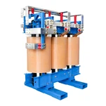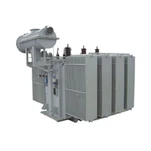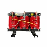


What Is Basic Impulse Insulation Level (BIL) and Why Does It Dictate Transformer Dielectric Design?
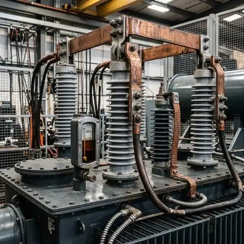
Basic Impulse Insulation Level (BIL) is the reference level of insulation expressed as the crest value of a standard lightning impulse withstand voltage. Transformer dielectric design must withstand atmospheric lightning, switching transients, and microsecond-scale overvoltages without electrical breakdown or destructive partial discharge.
For a 34.5 kV solar collection transformer installed at 2,150 meters, external air density derating reduced the bushing strike distance by over 12%. Upgrading the external bushing assembly from 150 kV to a 200 kV BIL class restored the required impulse withstand margin. This example shows why transformer basic impulse insulation level must be selected together with site altitude, external clearances, and surge protection.
Comparing Standard BIL Ratings: IEEE C57.12.00 vs. IEC 60076-3 Standards
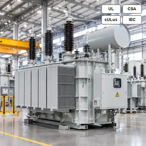
The North American IEEE C57.12.00 BIL standards and the international IEC 60076-3 specifications use distinct insulation classes and test terminology. IEEE commonly specifies BIL levels by nominal system voltage, while IEC uses Lightning Impulse Withstand (LI) and Power Frequency Short-Duration AC Withstand (AV) ratings.
| Nominal System Voltage (kV) | IEEE Std BIL (kV Crest) | IEEE Reduced / Optional BIL | IEC 60076-3 Standard BIL | Power Frequency AC Withstand (kV) |
|---|---|---|---|---|
| 4.16 kV | 60 kV | 45 kV / 75 kV | 60 kV | 19 kV |
| 13.8 kV / 12.47 kV | 95 kV | 75 kV / 110 kV | 95 kV / 125 kV | 34 kV |
| 24.94 kV | 125 kV | 150 kV | 125 kV / 145 kV | 50 kV |
| 34.5 kV | 150 kV | 125 kV / 200 kV | 170 kV / 200 kV | 70 kV |
| 69 kV | 350 kV | 250 kV / 300 kV | 325 kV / 350 kV | 140 kV |
| 115 kV | 550 kV | 450 kV / 650 kV | 550 kV | 230 kV |
| 138 kV | 650 kV | 550 kV / 750 kV | 650 kV | 275 kV |
| 230 kV | 900 kV | 750 kV / 1050 kV | 850 kV / 950 kV / 1050 kV | 395 kV / 460 kV |
Reduced BIL can lower transformer manufacturing cost when station-class metal-oxide surge arresters are correctly coordinated and installed close to the high-voltage bushings.
High-Altitude Derating and Environmental Multipliers: Calculating Dielectric Clearances Above 1000 Meters
Standard transformer insulation assumes operation at 1,000 meters or below. Above this elevation, reduced atmospheric pressure lowers the dielectric breakdown strength of external air clearances across bushing porcelain and composite sheds. Internal oil insulation does not lose dielectric strength with altitude, but external strike and creepage distances require correction.
For IEEE C57.12.00 BIL applications, the altitude correction factor may be calculated as:
ka = 1 + [(Altitude in Meters - 1000) / 10000]
At 2,500 meters, ka equals 1.15. A 150 kV BIL requirement therefore gives 172.5 kV crest, leading to selection of a 200 kV BIL-class external bushing.
Surge Arrester Insulation Coordination: Calculating the Margin of Protection
A robust transformer basic impulse insulation level is only effective when protected by proper surge arrester insulation coordination. IEEE C62.22 and IEEE C57.12.00 establish the lightning impulse Margin of Protection:
MP1 = [(Transformer BIL / Arrester Lightning Protective Level LPL) - 1] × 100%
Industry practice commonly requires at least 20% lightning impulse margin and 15% switching surge margin. For a 95 kV BIL transformer protected by a 36 kV LPL arrester, MP1 is 163.8%, well above the minimum threshold. Arresters should be located immediately adjacent to transformer bushings to limit traveling-wave reflections.
Factory Lightning Impulse Testing Protocols: IEEE C57.12.90 and IEC 60076-3 Execution
Per the official IEEE C57.12.90 test code, a transformer lightning impulse test uses a reduced full wave, chopped waves, and final full waves generated by a multi-stage impulse generator. Oscillograms of voltage and neutral current verify that no inter-turn puncture, layer breakdown, or core-shield defect occurred.
- Reduced full wave: establishes baseline voltage and current oscillograms.
- Chopped waves: apply high stress to simulate external flashover and verify inter-turn insulation.
- Full waves: confirm no permanent dielectric breakdown.
Ryan Electric Engineering: Precision Dielectric Design and Joint Venture Rigor
Ryan Electric applies insulation coordination, electrostatic finite element analysis, continuous-disc winding technology, and high-voltage testing across distribution and power transformer projects. Automated vacuum pressure drying and controlled oil impregnation support low partial discharge and full BIL compliance.
Actionable RFQ Sizing Checklist: How to Specify Transformer BIL in Your Next Tender
Include the complete voltage profile and grounding configuration, site elevation and ambient pollution severity, arrester MCOV and protective levels, and factory full-wave or chopped-wave impulse test requirements. Consult Ryan Electric engineering to calculate insulation margins and select UL/CSA-certified transformers for your grid.
- Voltage profile and grounding: state nominal voltage, Um, and grounding method.
- Site conditions: state elevation above 1,000 meters and pollution severity.
- Arrester parameters: specify MCOV, LPL/SPL, and mounting arrangement.
- Factory tests: state routine, type, or special impulse test and oscillogram reporting.
About the Author
This technical guide was authored by the High-Voltage Engineering & Insulation Coordination Team at Ryan Electric. With over 18 years of manufacturing expertise and certifications spanning UL, CSA, CE, DEKRA, and CNAS, Ryan Electric delivers precision-engineered liquid-immersed and dry-type transformers worldwide.