

A contractor in Northern Virginia sent us a single-line in March with a problem that has stopped being unusual. The first halls of a data center campus were live, the utility had moved the firm interconnection date from 2027 to 2031, and the developer had decided to run the site on its own generation instead. The transformer lineup on that drawing had been specified against a stiff utility source. Behind a generator, none of the numbers hold.
The queue data explains why more owners are making that call. The Berkeley Lab Queued Up: 2026 Edition counted roughly 1,312 GW of generation and 749 GW of storage actively seeking U.S. grid interconnection at the end of 2025, with a median of more than five years from request to commercial operation for the projects that got through in 2025. When a utility cannot promise a date, on-site generation stops being a backup plan and becomes the design basis.
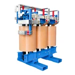
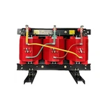
That is why the dry type transformer for data center specification stops being a catalog order the moment island operation enters the scope. The hardware is still a dry type transformer. The duty behind it is a different animal.

Island Mode Is a Different Electrical World
A transformer fed from a utility feeder sits behind a source that behaves almost like an infinite bus. At the 480 V secondary of a 2,500 kVA unit, available fault current typically runs 20 kA to 25 kA, voltage holds within a percent or two through load steps, and frequency is held by every machine on the far side of the substation. Put a 3 MW generator in front of the same bus and the picture inverts. Available fault current falls to roughly 2 kA to 4 kA, frequency can dip a hertz or two during a block load pickup, and source impedance is now dominated by generator subtransient reactance rather than by the network.
None of that damages a transformer as a piece of hardware. It damages every specification decision wrapped around one: protection settings, grounding method, impedance selection, and the derating you have to prove on paper. IEEE 1547-2018, the interconnection standard that also defines how islanding is detected and managed, treats these as system-level requirements for exactly this reason. The source sets the rules, not the load.
In our factory this shows up as a drawing review, not a winding change. When a North American contractor sends a single-line for a generator-backed data hall, the first thing our application engineers circle is the grounding note. If it still reads solidly grounded wye and the site will run islanded, we flag it before a single lamination is cut, because a ground fault study built on 25 kA of utility fault current tells you nothing about what happens behind a 3 MW genset.
Fault Current Comes First, and It Sets the Grounding
Here is the part most buyers miss. Overcurrent devices and relays are selected against the fault current available at the bus. Change the source from the utility to a generator and that current is simply not there any more - a ground fault on a solidly grounded wye can produce a current that sits below every protection threshold on the drawing, which is how you end up with a fault that burns until someone notices the smell.
The usual answer is high-resistance grounding: a neutral grounding resistor (NGR) on the transformer secondary that holds ground fault current to roughly 5 A to 10 A, paired with a detection relay that alarms or trips on that small current. NEC 250.36 allows the arrangement on 3-phase, 3-wire systems with no line-to-neutral loads, which is the shape of most data hall distribution because the loads are three-phase UPS modules and PDUs. Where line-to-neutral loads must be served, engineers either move to a low-resistance scheme or add a zigzag grounding transformer on a separate bus.
Two more items travel with the grounding decision. The first is an electrostatic shield between primary and secondary windings. On an islanded bus the electrical noise floor is different, and common-mode transfer matters to servers in a way it never matters to a motor load. The second is a neutral sized for triplen harmonics. A standard neutral on a heavily electronic load is a warranty conversation waiting to happen.
Step Loads and Harmonics Are the Two Real Design Drivers
A generator does not behave like a feeder when load reappears. During transition and recovery, blocks of chillers, UPS modules and PDUs reconnect within seconds, and the transformer sees step changes with a DC offset on the magnetizing branch. The unit has to ride through that without saturating into a nuisance trip or drifting into a buzz that the facility team will hear from the hall next door.
The second driver is harmonic content. Double-conversion UPS modules and rectifier front ends produce 5th and 7th harmonic currents plus triplen harmonics that add in the neutral instead of cancelling. Those currents do not heat a transformer the way fundamental current does; they concentrate in winding eddy losses and stray losses. IEEE C57.110 gives the derating method, and the practical outputs are a K-factor rating (K-13 or K-20 where a UPS fleet dominates the load), a harmonic loss factor, and a documented winding rise limit.
Current THD at a data hall low-voltage bus typically lands between 12% and 15% during a UPS recharge cycle. A K-1 general purpose unit sized on fundamental current would look fine on paper and run hot in service; at that spectrum the correct answer is a K-13 dry type with a double neutral, not a bigger frame. Meter the spectrum before you size.
What a Dry Type Transformer for Data Center Duty Needs That a Utility-Fed Unit Does Not
| Specification item | Utility-fed baseline | Island-mode duty |
|---|---|---|
| Available fault current at LV bus | 20–25 kA | 2–4 kA |
| Grounding | Solidly grounded wye | High-resistance grounded wye, 5–10 A NGR |
| Winding impedance | Set for coordination and voltage drop | Set low enough that protection still sees the fault |
| Neutral | Standard, sized for fundamental current | Double neutral for triplen harmonics |
| K-factor | K-1 to K-4 | K-13 or K-20 where a UPS fleet dominates |
| Winding shield | Often omitted | Electrostatic shield between windings |
| Overload documentation | Nameplate continuous rating | Documented step-load and short-time capability |
Impedance is where the two duty profiles actually collide. Lower impedance limits voltage dip during motor and UPS step loads, which is the classic reason islanded systems want a lower percentage impedance. Lower impedance also raises fault current, and fault current is the one thing a generator can barely supply. Pick the impedance on the protection study, not on the voltage drop spreadsheet alone.
Read the table as a list of questions for your supplier rather than a shopping list. Ask for loss data at the K-factor you actually need, ask for the neutral and the shield as separate line items so they cannot quietly disappear to protect a price, and ask what overload the design documents beyond nameplate. The answers change the lamination stack and the winding build, not just the print on the nameplate.

Open Transition, Closed Transition, and What the Unit Actually Survives
Island operation is not a state, it is a transition. Open transition means a dead bus: the transformer is de-energized for a moment and then re-energized from the generator, which is the harshest half-cycle it will see all year, because residual core flux and the closing angle can push inrush well above rated current. Closed transition means the generator and the utility are briefly paralleled, usually for under 100 ms, which requires matched voltage, matched phase rotation and matched impedance.
For paralleling we keep to a rule of thumb of impedance within about ±10% between units and identical vector groups. A delta-wye dry type paralleled against a wye-wye generator step-up transformer with a 30-degree phase shift will circulate current from the moment the closing relay operates. That is why the vector group belongs in the protection engineer's drawing set from the start, not chosen from whatever is on the shelf when the switchgear ships.
What we run in the factory before a unit leaves for a generator-backed site: turns ratio on every tap, impedance, no-load and load loss, applied potential, induced potential, partial discharge, and temperature rise on the type-tested design. For islanded sites we also hand over excitation and inrush data in a form the protection engineer can load straight into the relay model.
The Ryan Electric View
Ryan Electric has been building transformers since 2007 out of a 120,000 m² manufacturing base with more than 180 sets of production and test equipment and 37 registered patents. Since 2023 we have been an official joint-venture partner of Eaton. That relationship carries more weight on generator-backed projects than on standard ones, because island-mode designs get reviewed by protection consultants who expect a supply chain that can answer engineering questions rather than reissue a quotation.
Certification is not a formality on these jobs. Dry type units ship UL listed, with CSA certification and cULus marking for Canadian sites, and the medium-voltage dry types are built and tested to UL 1562 while the low-voltage end sits under UL 1561. DEKRA and CNAS lab reports travel with the routine and type tests, and where a specification references IEC 60076-11 for dry types we build to it in parallel rather than asking you to choose a side.
We are one UL listed transformer supplier among several, and we are not going to pretend that island-mode duty is routine work. It is not - it is a duty profile that has to be argued through a protection study, a grounding decision and a harmonic spectrum before a winding is designed. Buyers who shortlist a UL listed transformer supplier on price alone tend to discover that difference during commissioning, when the ground fault relay will not pick up and nobody can explain why.
A Checklist Before You Order
Send these seven items with the RFQ and the data center transformer specifications you get back will actually fit the site:
- Fault current at the LV bus with the generator as source - not the utility value copied from an earlier drawing
- Grounding scheme and NGR rating - plus whether any line-to-neutral load exists
- Transition method - open, closed, or soft-load transfer, and how long the bus is dead
- Measured harmonic spectrum - and the K-factor it implies, not a K-factor borrowed from a template
- Step-load sizes and expected recovery time - the numbers the genset supplier gave you, in kVA and seconds
- Vector group and impedance of every unit that will parallel - including the generator step-up transformer
- Certification set required at destination - UL, cULus, CSA or IEC, and the test reports you want delivered with the unit
Island-mode data center transformer specifications are one of the few places where a ten-minute conversation at RFQ stage saves a redesign at commissioning. Treat the dry type transformer for data center duty as a protection device that happens to have a core inside it, and specify it that way. Send us the single-line, the load list and the destination country, and our application engineers will come back with a specification you can hand straight to the protection consultant.
About the Author: Written by the engineering and application team at Ryan Electric, an Eaton joint venture partner and UL/CSA-certified manufacturer of dry type, oil-immersed and pad-mounted transformers, serving data center, industrial, utility and renewable projects across North America, the Middle East, Southeast Asia and Africa.