

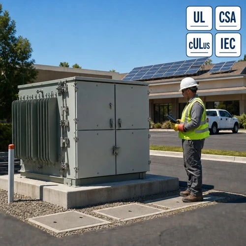
A 500 kVA distribution transformer does not become a different machine when current starts flowing the other way. It becomes a machine whose tap setting, harmonic duty, loss weighting and protection coordination were chosen for an assumption that no longer holds - and none of the four shows up as a defect on a routine test report. That gap is where feeder studies stall, and where over-voltage complaints come from.
The condition behind most of those calls is reverse power flow: midday current leaving the load side of the transformer and travelling back up the feeder. On feeders with heavy rooftop solar or commercial storage it is a scheduled operating condition, not a curiosity.
Why Reverse Power Flow Stopped Being an Edge Case
Berkeley Lab publishes project-level data on roughly 5.3 million distributed solar and storage systems installed in the United States through the end of 2025. The dataset is open and the trend line is not subtle: the Berkeley Lab Tracking the Sun database (https://emp.lbl.gov/tracking-the-sun) is what utility planners use to model where export appears next.
What those systems may do at the point of interconnection is set by IEEE 1547-2018 (https://standards.ieee.org/ieee/1547/5915/), the active DER interconnection standard. Its scope is instructive for a transformer buyer: it covers DER connected at typical primary and secondary distribution voltages, treats radial primary and secondary distribution systems as the main case, and fixes the abnormal-condition, power-quality and islanding behaviour the transformer has to live with.
The arithmetic on the feeder is simple. A circuit designed so current always travelled from substation to load now has hours in which the distributed energy resources behind a single pad mounted transformer exceed that section load. Current enters the low-voltage winding and leaves through the high-voltage winding, so the unit steps up and the feeder sees a source where it previously saw a sink.
Most datasheets we receive still describe a transformer that is the source of voltage rise and a feeder that absorbs it - backwards for four midday hours.
What Reverses Inside the Transformer - and What Does Not
Copper does not care about direction. Load loss stays proportional to current squared whether current enters the high-voltage winding or leaves it, and core loss is unchanged. That is the reassuring half, and it is also why reverse power flow hides so well: a unit in reverse flow can pass a ratio test, a winding resistance test and a dissolved gas analysis with nothing to report.
Everything built on a voltage-drop assumption cares very much. On a radial feeder, voltage falls as current moves away from the substation and the tap is set to compensate. Reverse the current and the same impedance produces a voltage rise instead of a drop, so a tap that was fighting a 3% forward drop starts adding voltage to a network that already has too much. On four-wire, multi-grounded secondaries the neutral current reverses too, and the grounding electrode system becomes the return path for exported current.
Thermal duty changes with the profile. A unit that once ran one evening peak now runs a near-rated-current export window at midday and a forward peak after sunset, so insulation ages on hottest-spot temperature and time together.
The tap-setting trap
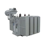
A cooperative engineer in the U.S. Southwest sent us a 500 kVA three-phase pad-mounted specification for a feeder where rooftop PV had reached roughly 30% of daytime minimum load. The datasheet was clean and the tap was still at +2.5% above nominal - set years earlier to fight forward drop on a longer circuit. On a clear April afternoon it pushed the secondary above the utility voltage band with the unit barely loaded. The fix cost nothing in copper: a tap change, a re-issued nameplate, one crane visit.
Specification Changes That Matter on a DER-Heavy Feeder
This is the list we work through when a buyer tells us the feeder will see two-way power.
| Item | One-way specification | Reverse-flow-ready specification |
| Tap arrangement | Two 2.5% taps above and two below nominal, set against forward voltage drop | Tap selected against the worse of the forward and reverse voltage conditions, then locked and photographed |
| Voltage check | Checked at peak load only | Checked against the utility service-voltage band at peak forward load and peak export |
| Harmonic duty | Standard unit, no harmonic allowance | Harmonic-loss allowance or a stated K-factor sized to the measured inverter current spectrum |
| Loss weighting | Load loss carries most of the evaluated cost | No-load loss weighted higher, because export hours add core-loss hours at low load |
| Temperature rise | 65 °C average winding rise | 55 °C rise where bidirectional peaks coincide with a hot pad or a poorly ventilated vault |
| Low-voltage interface | LV terminals and neutral sized for load current | LV terminals, neutral and bushing arrangement sized for export current |
| Protection | Devices coordinated for utility-side fault current only | Coordination that includes DER backfeed contribution through the transformer |
| Nameplate and documents | Routine test report | Routine test report plus measured no-load and load loss, tap record and harmonic-loss statement |
Three of these items are free and two move the price. Tap selection, nameplate marking and documented loss figures cost nothing beyond discipline. A harmonic allowance and a 55 °C rise design cost copper and core, and both have to be justified by feeder data rather than preference.
Not sure which of the eight applies to your circuit? Send us the one-line diagram and the daytime minimum load through ryan-transformers.com and our engineers will work through the list with you before the order is placed.
Why the loss weighting flips
Present-worth evaluation puts a dollar value per watt of no-load loss against a dollar value per watt of load loss, discounted over unit life. No-load loss accrues in every hour of the year; load loss accrues with the square of the load. A feeder with a long export window keeps its core-loss hours and shifts the load-loss hours to a lower-current part of the day, which flips the weighting toward better core steel.
Protection When the Load Side Can Push Current
A transformer that can be back-fed is a coordination problem before it is a purchasing problem. When a fault occurs on the utility side, distributed energy resources downstream keep pushing current into it - through the transformer, from low-voltage winding to high-voltage winding - and the high-voltage fuse never sees that contribution, because the current does not pass through it in the forward direction.
Four items belong in the transformer conversation rather than in a later study: directional overcurrent where generation connects, the reverse-fed fault clearing time the windings can tolerate, reclosing while the feeder is still back-fed, and unintentional islanding. Ask for the utility protection study - or at minimum the DER aggregate nameplate and through-fault expectation - with the specification, because it sets the low-voltage breaker selection and, occasionally, the percent impedance.
Heat, Harmonics and Aging: Three Numbers for the RFQ
The first number is 65 °C, the average winding temperature rise at rated load for which the insulation system of a typical liquid-immersed distribution transformer is designed. It is also the assumption that bidirectional loading quietly breaks, because the unit is now asked to absorb two peaks a day in an ambient it cannot control.
The second is the loading guide. IEEE C57.91-2025 (https://standards.ieee.org/ieee/C57.91/7163) sets out how loading above nameplate affects insulation, produces gas in the oil and reduces life, and how ambient temperature, altitude and cooling method change the capacity you actually have. Industry practice treats insulation life as roughly halving for every 6 to 8 °C above the reference hottest-spot temperature.
The third is distortion. IEEE 519-2022 (https://standards.ieee.org/ieee/519/10677/) establishes voltage and current waveform distortion goals at the point of common coupling. Inverter-based generation is a nonlinear source, and the harmonic current it injects heats windings and tank steel in ways a 60 Hz load model misses. Ask for the measured current spectrum, then accept a stated K-factor or a harmonic-loss allowance.
Two daily peaks, a hot pad and a harmonic-rich current add losses and ageing to a unit sized for one peak and a clean waveform.
What We Verify in the Factory Before a Reverse-Flow-Ready Unit Ships
Ryan Electric has manufactured oil-immersed transformers since 2007 and has been an Eaton joint venture partner since 2023. Our Jiangsu plant covers 120,000 m² with more than 180 sets of production equipment and 37 patents, and the portfolio carries UL, CSA, IEEE, DEKRA, CNAS and CE certification. Two-way duty units go through the standard routine test bay with five additional items on the same certificate as a pad mounted transformer manufacturer package:
- Tap position record - the tap actually fitted, photographed on the nameplate before the cover is bolted.
- No-load and load loss measured at 50% and 100% per-unit load - so the buyer can run a loss evaluation on real numbers instead of a guaranteed maximum.
- Temperature-rise verification against the ordered rise class - 65 °C for standard units, 55 °C where the feeder study called for thermal headroom.
- Harmonic-loss or K-factor verification - where the specification includes a distortion allowance, the design check is recorded rather than assumed.
- Nameplate and document package - ratio, impedance, loss figures, certification mark, serial number and the reverse-feed provision noted on the nameplate.

Field mistakes still cost more than factory ones. The recurring three on two-way feeders are a tap left at the old setting after a feeder reconfiguration, a neutral sized for the original forward load, and a protection study that predates the first commercial array on the circuit.
Send the Feeder Data Before You Send the Purchase Order
If your circuit is heading toward reverse power flow, five documents turn a general conversation into a quotable specification:
- The feeder one-line, showing where the transformer sits relative to the substation and the generation.
- Aggregate generation nameplate behind the transformer, by technology - PV, storage, combined heat and power.
- Daytime minimum load and evening peak, taken from interval data rather than annual averages.
- The utility service-voltage band and the tap preference, including whether they want the tap set for the export or the import condition.
- The certification target - UL or cULus listing for U.S. projects, CSA certification for Canadian ones, with the distortion allowance stated in the specification.
Send those five items through ryan-transformers.com and our engineers will return a tank drawing, a tap recommendation and a loss evaluation built on your own load profile. The cost of skipping that step shows up as a crane visit and a voltage complaint, usually in the second summer.
About the Author: This article was written by the engineering team at Ryan Electric, a UL/CSA-certified transformer manufacturer in Jiangsu, China, supplying oil-immersed and dry-type transformers to utility, data center, industrial and renewable projects across North America, the Middle East, Southeast Asia and Africa.