

A contractor in Northern Virginia sent us a single-line diagram last month with one line of text attached. The owner wanted 800 VDC racks inside a building that was permitted around 480 V AC. His question was not about power supplies, busway or rack PDUs. It was about the transformers he still had to buy, and what had to change about them.
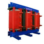
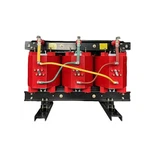
The short answer: the 800 VDC transition does not remove the transformer from an AI data center. It relocates it, hardens its duty, and squeezes its tolerances. For anyone buying a dry type transformer for data center work in 2026, that distinction decides how the next three years of orders get specified.
What NVIDIA, Google and Microsoft Just Standardized
The 54 VDC rack bus that carried data centers for two decades has run out of headroom. As accelerator racks climb toward megawatt density, the copper needed to move that current at low voltage becomes the constraint, and every extra AC-to-DC conversion stage between the utility service and the GPU burns efficiency operators can no longer spare.
NVIDIA, Google and Microsoft have developed the 800 VDC architecture together through the Open Compute Project. The group published a joint low-voltage DC white paper in March 2026 and the LVDC Solid-State Transformer Specification v0.3 in July 2026, and according to the NVIDIA 800 VDC announcement more than 80 equipment manufacturers and infrastructure companies are already building products against that specification. Wood Mackenzie projects USD 9 trillion in global AI and data infrastructure investment through 2040.
Three deployment stages are defined and they arrive at different times. An MGX-compatible 800 VDC power rack ships in the second half of 2026 and slots into an existing AC facility inside the row, so the building electrical system stays untouched. A row power center using overhead 800 VDC busway carries up to 2 MW per row from 2027. The facility-scale DC power block, converting grid power directly to 800 VDC in a single step, is the first architecture that touches the medium-voltage transformer head-on.
Why 800 VDC Relocates the Transformer Instead of Removing It
Read the OCP Solid-State Transformer specification closely and the transformer story changes shape rather than ending. A medium-voltage solid-state transformer (MVSST) is defined there as a megawatt-scale power electronic converter, offered in two upstream configurations: 13.8 kV and 34.5 kV, three-phase three-wire plus PE, with DC output ratings of 5 MW and 10 MW respectively. In the native 800 VDC design, that converter absorbs the role of the conventional 50/60 Hz line-frequency medium-voltage transformer, the rectifier unit, and part of the UPS function.
That is where the confusion starts. Engineers read "the solid-state transformer replaces the transformer" and conclude that magnetics are leaving the building. The specification itself shows why they are not. The MVSST still presents a medium-voltage AC interface upstream, and the document requires it to be fed from a transformer secondary configured as Wye with a low-resistance grounded or solidly grounded neutral. Something still has to transform medium-voltage AC and provide the DC bus grounding reference.
Where the transformer still sits in an 800 VDC facility
| Architecture stage | Transformer still required | What changes in the specification |
|---|---|---|
| Utility service entrance (MV) | Oil-immersed or dry-type medium-voltage service transformer | Duty largely unchanged; delta-wye with low-resistance or solid grounding, 13.8 kV or 34.5 kV |
| Hybrid row (existing AC building) | Dry-type step-down transformer feeding row-level AC-to-DC conversion | Higher harmonic current content; K-factor rating and documented derating required |
| Native 800 VDC (DC power block) | MVSST replaces the line-frequency unit; MV isolation and grounding transformers may still apply | Power-electronics duty, IEEE 519 harmonic limits, ride-through and ramp-rate coordination |
| Auxiliary and controls | Small 480 V dry-type transformer | UPS-backed supply, low no-load loss, sealed or nonventilated construction |
What Actually Changes in a Dry Type Transformer for Data Center Duty
Four things change when a line-frequency transformer feeds a rectifier front end. None are exotic, and all four are documentable before you place an order.
Harmonic duty stops being a rounding error. A rectifier front end draws non-sinusoidal current, and the resulting eddy losses land in the windings and stray losses in the core clamps. IEEE 519 sets the harmonic current limits the utility holds you to at the point of common coupling, but it says nothing about what the transformer does internally. That is a K-factor and derating question, answered with the actual harmonic spectrum rather than a generic assumption.
The voltage-regulation budget gets consumed upstream. The OCP specification holds the DC output to about 0.5% switching ripple, 1% static tolerance and 3% dynamic regulation. Part of that budget is eaten by the medium-voltage transformer's own impedance drop when load swings, and the same document sets utility-side load acceptance and rejection at roughly 20 to 50 MW per minute. Percent impedance stops being only a fault-current number and becomes a control-loop parameter.
Overload behaviour has to be proven, not assumed. Fault coordination in the specification is written as 150% of rated current in constant-current mode for 150 milliseconds, with an allowed trip afterwards, plus 120% for 5 seconds in constant-voltage mode. A dry-type transformer can ride through that window, but only if its thermal margin has been engineered and documented before the unit is built.
The physical envelope gets tight. The MVSST envelope in the specification runs 10 to 20 ft long, 8 ft deep and 8.5 ft high, with the height limit driven by transport and field serviceability. The same constraints push dry-type construction indoors on the AC side: no oil, no vault, no containment. The environmental duty is not gentle - NEMA 3R outdoor rating, C5 corrosion class, operation from −30 °C to 40 °C with a derating factor above 40 °C, and seismic design category D at an SDS of 1.193 g.

Certification: DOE Covers Less Than Most Buyers Think
In the U.S., the energy conservation standards for distribution transformers are written around a definition rather than around a product family. Under 10 CFR 431.192 a distribution transformer has an input voltage of 34.5 kV or less, an output voltage of 600 V or less, operates at 60 Hz, and is rated 10 to 2,500 kVA for liquid-immersed units or 15 to 2,500 kVA for dry-type units. Compliance with the amended standards is required on and after 23 April 2029, as confirmed on the U.S. Department of Energy distribution transformer page.
The exclusions matter more for data center work than the inclusions. Rectifier transformers, nonventilated transformers, sealed transformers, drive or isolation transformers, special-impedance transformers, uninterruptible power supply transformers and grounding transformers all sit outside the covered definition. Several describe precisely the equipment sitting inside an 800 VDC row.
So "DOE compliant" is a regulatory floor, not a specification, and it may not even apply to the unit on your drawing.
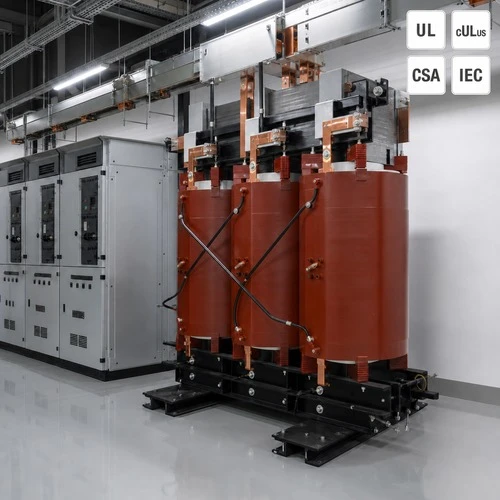
The safety certification path runs on voltage class. UL 1561 governs air-cooled, dry, ventilated and nonventilated general-purpose and power transformers in the 600 V class and below; medium-voltage dry-type units sit under UL 1562. Canadian projects need the cULus marking or the CSA C22.2 route, and a UL listed transformer file is only valid for the exact rating, winding material, insulation class and enclosure it was evaluated against, not for the product family. The OCP specification routes the converter itself through a different standard set, including UL 347A, UL 508C and UL 1741, with IEEE 519 for harmonics and IEEE 693 for seismic. Expect to manage both sets on the same project.
What We Ask Before We Quote
When a data center integrator sends us an RFQ for row equipment, the first question our engineers ask is rarely the kVA. It is the harmonic spectrum the rectifier front end will present, how fast the load steps in MW per second, and how long the unit has to hold through a ride-through event. Those three answers change the design more than the kVA figure does.
One project is worth repeating. A colocation developer in Texas specified 2,500 kVA by arithmetic, meaning connected load plus a 20% margin, the way you would size an office building. We asked for the load profile instead. The duty was a rectifier-fed row with roughly 30% harmonic current content and a load step repeating every 90 seconds. A general-purpose unit would have carried that on paper and run hot. The order that shipped used a K-13 rated core with a documented 150% / 150 ms capability, and the difference was one frame size plus a test report, not a redesign.
UL listed transformer documentation works the same way. On North American dry-type orders we photograph the nameplate on the test bay floor before the unit is crated, because that is what an inspector reaches for first.
Here is the working checklist we hand to data center buyers, whether the project is hybrid or native 800 VDC:
• Harmonic spectrum, in percent by order rather than a single THD figure, plus the load step in MW per second.
• Ride-through requirement, expressed as time at a given percentage of rated current.
• Certification target and envelope limits, UL 1561 or UL 1562, cULus, CSA C22.2, and the height the door will actually allow.
Where Ryan Electric Fits
Our manufacturing base in Jiangsu covers 120,000 m², runs more than 180 sets of production and test equipment, and holds 37 patents, with UL, CSA, IEEE, DEKRA, CNAS and CE certifications across dry-type and liquid-immersed products. Since 2023 we have operated as an Eaton joint venture partner.
We build cast resin and VPI dry-type transformers, oil-immersed units from 10 kV up to 200 MVA, and pad-mounted designs for North American distribution. Rectifier duty, K-factor ratings, documented overload curves and seismic qualification are quoted as standard inputs rather than special requests, and the routine test report ships with temperature-rise data. On data center work our dry-type units have gone into colocation and industrial campus projects where the specification was written around harmonic content, redundancy and seismic category instead of nameplate kVA.
Ready to Spec for 800 VDC?
Start from the duty profile, not the nameplate. If you are planning an 800 VDC build or a hybrid transition row, send us the duty profile through ryan-transformers.com. We will come back with a K-factor rating, a documented overload curve and a schedule we can hold, rather than optimism about a dry type transformer for data center order nobody has fully specified yet.
About the Author: This article was written by the engineering team at Ryan Electric, an Eaton joint venture partner and UL/CSA-certified transformer manufacturer in Jiangsu, China, supplying dry-type, oil-immersed and pad-mounted transformers to data center, utility, renewable and industrial projects across North America, Latin America, Southeast Asia and the Middle East.