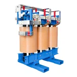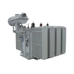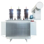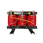


As renewable generation and battery energy storage systems (BESS) replace conventional thermal generation across North America, Australia, and Europe, regional transmission system operators are confronting a fundamental grid stability crisis: the loss of physical rotational inertia. To maintain grid frequency and voltage stability in low short-circuit ratio (SCR) interconnects, utilities are transitioning from traditional grid-following (GFL) controls to advanced grid-forming (GFM) architectures. However, deploying GFM inverters fundamentally alters the electrical and thermal stresses placed on the medium-voltage step-up transformer. In utility-scale solar and storage projects, selecting robust grid-forming inverter transformers is no longer an off-the-shelf catalog exercise-it is the core engineering decision that dictates whether a renewable facility survives transient grid events or trips out during critical frequency disturbances.
Unlike standard grid-following units that act as synchronized current sources, grid-forming inverters operate as independent voltage sources behind an internal virtual impedance. When a system fault or sudden phase angle jump occurs, GFM inverters deliver instantaneous active power, sub-cycle synthetic inertia, and sustained fault current. According to grid modernization standards published by the IEEE Standards Association on Interconnection and Interoperability of Inverter-Based Resources (IEEE 2800), high-penetration inverter zones require precise coordination between converter control loops and magnetics. Understanding how voltage source dynamics impact core flux density, transient overcurrent withstand, and transformer percent impedance is essential for project developers, EPCs, and substation design engineers.
Voltage Source Physics: Why Grid-Forming Controls Stress Step-Up Transformers
In a conventional grid-following system, the converter phase-locked loop (PLL) tracks the medium-voltage grid voltage and injects sinusoidal current accordingly. Under sudden grid faults or severe voltage sags, the GFL converter rapidly curtails current output to protect its internal semiconductors. In stark contrast, a grid-forming converter maintains its internal AC voltage phasor magnitude and angle. When grid voltage dips or phase angle shifts occur, the difference between the inverter internal voltage and the grid voltage forces immediate, unconstrained current flow across the medium-voltage step-up transformer.
This voltage-source behavior exposes grid-forming inverter transformers to severe sub-cycle transients. The transformer is directly in series with the grid stiffness; during phase angle jumps of 20° to 45° caused by line switching or remote three-phase faults, the instantaneous current through the low-voltage windings can peak at 2.0 to 3.0 per-unit (p.u.) of rated current within a few milliseconds. Inverters equipped with virtual synchronous machine (VSM) or droop control algorithms sustain these elevated currents for hundreds of milliseconds to support system frequency, generating significant electromagnetic forces and thermal spikes within the transformer windings.
Transient Overcurrent and Mechanical Withstand: Sizing for Sub-Cycle Fault Contribution
Standard distribution transformers designed under IEEE C57.12.00 or IEC 60076 standards are rated to withstand external short-circuit currents for 2.0 seconds based on thermal calculations. However, in GFM applications, the primary failure mechanism is not steady-state thermal rise, but repetitive mechanical fatigue resulting from sub-cycle peak electromagnetic forces. Because electromagnetic force is proportional to the square of the peak current (F ∝ I_peak^2), a 2.5 p.u. fault current burst produces over six times the mechanical stress experienced during normal rated operation.
When our engineering team commissioned a 3.45 MVA 34.5 kV step-up unit for a utility-scale BESS in west Texas, the interconnecting utility specifically scrutinized the mechanical clamping structure and core-and-coil bracing. During low-SCR grid contingency testing, the GFM inverters injected repetitive sub-transient current bursts to stabilize a local 138 kV bus. Standard radial spacers and friction clamping would have suffered progressive winding displacement over multiple fault cycles. To prevent axial and radial winding distortion, Ryan Electric engineers implement high-density pressboard radial spacers, pre-compressed coil clamping assemblies with constant-pressure disc springs, and epoxy-bonded Continuously Transposed Conductor (CTC) windings. This structural reinforcement ensures full compliance with mechanical withstand criteria under repeated fault events.
Core Saturation and DC Bias: Mitigating Flux Asymmetry During Phase Angle Jumps
One of the most insidious threats in GFM step-up substations is transient core saturation caused by DC flux offset. When a grid-forming inverter responds to a sudden voltage phase angle jump or asymmetric fault clearing, the voltage integral applied across the transformer core shifts dynamically. This introduces a transient DC offset into the core flux density, driving the core steel deep into the non-linear saturation knee.
If a transformer core is designed with an aggressive nominal magnetic flux density of 1.72 to 1.75 Tesla (T) to minimize footprint and material cost, even a 10% transient DC flux offset pushes the operating point beyond 1.90 T. Once core saturation occurs, the magnetizing inductance collapses, magnetizing current spikes dramatically to hundreds of amperes, and stray flux spills into the transformer tank walls and structural clamping plates. This results in severe localized overheating, intense acoustic noise, and spurious differential protection (87T) relay trips. To prevent core saturation in GFM systems, Ryan Electric specifies high-permeability, laser-scribed Grain-Oriented Electrical Steel (GOES) and designs the core with a conservative nominal flux density ceiling under 1.62 T at rated voltage. This provides a robust 15% flux margin to absorb transient DC offsets without entering saturation.
Optimizing Transformer Percent Impedance and Winding Resonance in Weak Grids
Selecting the appropriate transformer percent impedance (%Z) in grid-forming installations involves balancing two conflicting electrical requirements. On one hand, higher impedance helps limit peak short-circuit currents and protects the inverter IGBT bridges during dead-short faults. On the other hand, excessive impedance increases voltage drop across the transformer, weakens the voltage-source coupling between the GFM inverter and the transmission grid, and degrades the synthetic inertia delivery speed.
In weak grids with short-circuit ratios below 1.5, optimal system stability is typically achieved when transformer percent impedance is engineered within a tight band between 6.5% and 7.5% on the transformer base rating. Furthermore, transformer leakage inductance interacts directly with the inverter LC/LCL output filter and long underground collection cables. If the resonant frequency of this LC circuit aligns with inverter switching frequencies or sub-synchronous grid modes (5 Hz to 45 Hz), severe sub-synchronous resonance (SSR) can develop. Ryan Electric provides complete frequency-dependent impedance matrix models (R-L-C sweep from 10 Hz to 100 kHz) during the submittal phase, enabling EPCs to perform comprehensive electromagnetic transient (EMT) stability studies in PSCAD/EMTDC before equipment fabrication.
Dynamic Thermal Rating and Cyclic Loading Under Fast Frequency Response (FFR)
In commercial BESS and hybrid renewable power plants, grid-forming inverters provide Fast Frequency Response (FFR) and spinning reserve services. This service profile involves sudden transitions from float/standby mode (0% load) to 120% or 150% overload within 50 milliseconds upon detecting a grid frequency drop, holding that peak output for 15 to 30 minutes before tapering down. Designing for these dynamic duty cycles requires evaluating the transformer via dynamic thermal rating principles rather than static nameplate ratings.
Standard liquid-immersed transformers with mineral oil have a bulk oil thermal time constant of 2.5 to 3.5 hours, but the winding conductor hot-spot time constant is only 4 to 8 minutes. Under frequent FFR dispatches in high ambient environments (e.g., 45°C ambient in desert utility sites), repetitive thermal cycling accelerates cellulose insulation degradation and weakens gasket seals. Implementing synthetic or natural ester dielectric fluids (such as FR3) with high flash points (≥300°C) and Class 120 thermal insulation upgrades provides the required overload capability without sacrificing operational lifespan. Incorporating fiber-optic direct winding temperature sensors ensures accurate monitoring under dynamic load dispatch.
Engineering Comparison: Grid-Following vs. Grid-Forming Step-Up Transformers
| Design Parameter | Standard Grid-Following (GFL) Unit | Grid-Forming (GFM) Step-Up Unit |
|---|---|---|
| Inverter Source Behavior | Controlled current source; rapid current limiter clamp on fault | Voltage source behind virtual impedance; instantaneous current delivery |
| Peak Transient Current | Typically limited to 1.1–1.2 p.u. nominal current | Sub-cycle peak currents up to 2.0–3.0 p.u. during phase jumps |
| Nominal Core Flux Density | Standard 1.70–1.75 T design (optimized for footprint/cost) | Conservative ≤ 1.62 T design with ≥ 15% DC offset saturation margin |
| Mechanical Clamping | Standard structural tie plates and wood/pressboard blocks | Constant-pressure spring-loaded disc clamping & CTC windings |
| Percent Impedance (%Z) | Wide tolerance band (e.g., 5.75% ± 10%) | Tight tolerance band (6.5%–7.5% ± 5%) tailored for weak-grid stability |
| Duty Cycle & Overload | Smooth diurnal solar profile or continuous rated power | Dynamic FFR step-loads (120%–150% overload), requires dynamic thermal rating |
Why Utility EPCs Choose Ryan Electric as Their UL Listed Transformer Supplier
As a recognized UL listed transformer supplier with over 18 years of specialized engineering experience, Ryan Electric manufactures high-reliability step-up transformers tailored specifically for renewable energy, BESS skids, and grid-forming inverter applications. Operating from our state-of-the-art 120,000 m² manufacturing base equipped with over 180 advanced production units and holding 37 invention and utility patents, we engineer liquid-immersed and dry-type transformers rated up to 200 MVA and 230 kV.
Since 2023, Ryan Electric has operated as an official joint-venture partner with Eaton, combining global manufacturing best practices with localized utility engineering support. Every grid-forming inverter transformers unit manufactured in our facility undergo rigorous factory acceptance testing (FAT) under IEEE C57.12.90 and IEC 60076 standards, including lightning impulse (BIL) testing, partial discharge measurement, temperature rise testing with simulated harmonic spectrums, and sweep frequency response analysis (SFRA). Our products hold comprehensive certifications including UL Listing, CSA C22.2, IEEE, DEKRA, CNAS, and CE, providing utility buyers and EPC contractors with complete confidence during interconnection commissioning.
Engineering Checklist: Specifying Step-Up Transformers for GFM BESS and Solar Projects
When preparing a Request for Proposal (RFP) or technical specification for a grid-forming step-up substation, ensure the following parameters are explicitly defined:
1. Peak Fault Current Envelope: Specify maximum sub-transient peak current (e.g., 2.5 p.u.) and duration for mechanical bracing design.
2. Core Magnetic Flux Headroom: Mandate a maximum nominal core flux density below 1.65 T to provide DC flux offset ride-through.
3. %Z Impedance & Tolerance: Specify required transformer percent impedance (e.g., 7.0% at ONAN rating) with a ±5% tolerance band to avoid control loop de-tuning in weak grids.
4. Vector Group & Grounding: Standardize on Dyn11 or YNd11 to provide neutral grounding on the medium-voltage collector bus while trapping triplen harmonics on the delta inverter side.
5. Thermal Overload Profile: Define Fast Frequency Response (FFR) duty cycle duration and peak overload percentage to establish proper dynamic thermal rating design margins.
6. Dielectric Fluid Selection: Evaluate natural ester fluid (FR3) for fire-safe indoor/substation installations and enhanced thermal headroom.
7. Factory Certification & Quality: Partner with a proven UL listed transformer supplier that provides documented routine and type test reports validated by accredited laboratories.
To explore customized transformer engineering solutions for your next grid-forming BESS, solar, or hybrid microgrid project, visit our official technical portal at U.S. Department of Energy (DOE) Grid Modernization Resources or contact our engineering applications team at sales@ryan-transformers.com to discuss technical specifications and fast-track delivery schedules.
About the Author
Senior Power System Applications Engineering Team - Ryan Electric
Ryan Electric (&瑞安电气) is a global manufacturer of medium- and high-voltage power transformers, cast resin dry-type transformers, and pad-mounted substation units. Backed by our Eaton joint-venture engineering standards and comprehensive UL, CSA, IEEE, and CE certifications, we deliver reliable, custom-engineered power transformation solutions to top-tier utilities, renewable energy developers, and industrial EPCs worldwide. Learn more at https://www.ryan-transformers.com.