

The primary compartment is the least discussed part of a transformer order, and it is the reason most pad-mounted units get held at the point of energization. A distribution engineer we work with found that out the hard way: his purchase order called for a loop feed pad-mounted transformer on a 25 kV ring, two primary ways, external switch handles. The drawing package that came back from his own design team showed a single primary way. On a looped circuit that is not a cosmetic difference. The unit cannot be sectionalized, and the utility's commissioning inspector will not connect it.
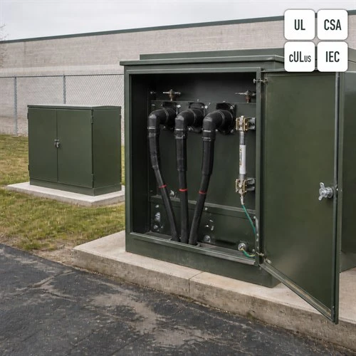
What Loop Feed Actually Changes on the Pad
Start with the circuit, not with the transformer. A radial feed unit sits at the end of a single primary run: one set of high-voltage ways, one cable, no switching duty beyond its own internal fuse. A loop feed pad-mounted transformer sits inside a ring. Two primary ways let the incoming cable land on one set of bushing wells while the outgoing cable leaves from the second set and continues to the next transformer on the circuit.
That second way is what buys a utility its restoration strategy. When a cable section between two pad-mounted units fails, a crew opens the load-break way on either side of the fault, isolates the damaged section, and back-feeds the remainder of the loop from the other direction. On a commercial or residential feeder, that is the difference between a two-hour switching operation and an afternoon of outage for every customer downstream.
The arrangement is standardized, not a manufacturer preference. IEEE Std C57.12.34-2022 covers the connector, bushing and terminal arrangements for radial or loop-feed systems on three-phase, 60 Hz, liquid-immersed, self-cooled, compartmental-type transformers rated 10 MVA and smaller at 34.5 kV nominal system voltage and below. The scope is worth reading before you write a specification: IEEE C57.12.34-2022 standard page.
Loop feed is not free. You pay for a second set of bushing wells and inserts, a wider primary compartment, two cable terminations instead of one, and on many utility specifications two externally operable switch handles. The extra hardware is a modest share of the installed cost of the circuit it protects, and it looks very small next to the cost of a unit that has to be reworked after the utility rejects it at the pad. Against that, a radial feed design is simpler and cheaper to build, which is why it still makes sense at the end of a dedicated service run where no other customer shares the cable.
| Parameter | Radial feed | Loop feed |
|---|---|---|
| Primary ways on the unit | 1 | 2 (in and out) |
| Typical connector class | 200 A load-break or 600 A deadbreak | 200 A load-break inserts, or 600 A deadbreak on mainline loops |
| Switching under load | Not normally required | Required, with the circuit energized |
| Restoration after a cable fault | Unit stays out until the cable is repaired | Loop is sectionalized; unaffected units stay energized |
| Typical application | End-of-line commercial or industrial service | Residential and commercial rings, campus distribution |
| Compartment and hardware | Smaller primary compartment, one cable termination | Wider compartment, two terminations, extra inserts and handles |
The Primary Interface: 200 A Load-Break vs 600 A Deadbreak
Pad-mounted units built for North America are dead-front: there are no exposed live parts inside the primary compartment. Connection is made with shielded separable insulated connectors, the elbows most line crews know on sight. Ratings, interchangeability and test requirements for those connectors come from IEEE Std 386, whose 2025 edition covers loadbreak and deadbreak separable insulated connector systems for distribution systems rated 2.5 kV through 35 kV and 900 A or less: IEEE Std 386-2025.
The distinction that decides your design is whether the connector can be operated while energized. A 200 A load-break elbow opens under load with a hot stick, which is exactly how a crew isolates one section of a loop without dropping the rest of it. A 600 A deadbreak connector is not a load-switching device: the circuit must be de-energized before the connector is separated. Where a loop carries the combined current of several downstream units, the through-current approaches the 200 A rating and the design moves to 600 A deadbreak bushings and larger cable.
Put numbers on it. At 15 kV, a 200 A interface corresponds to roughly 5.2 MVA of through-load (the square root of 3, times 15 kV, times 200 A). The same interface rated 600 A corresponds to about 15.6 MVA. Three 1,000 kVA commercial units fed through one loop position are already sitting on the edge of a 200 A way, which is why the utility's switching philosophy usually settles the question before the transformer rating does.
The rating that gets forgotten is fault close. Separable connectors carry separate continuous, switching and fault-close ratings, and the fault-close rating has to exceed the available fault current at the pad, because someone will eventually close an elbow onto a faulted cable. Fault closure is an actual test requirement in IEEE Std 386, not an assumed property of a moulded part.
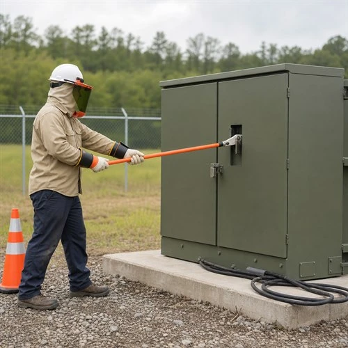
If you want one readable reference on how this equipment is specified in North America, Eaton fundamentals of medium-voltage transformers is a good starting point. It is the same document our own engineers keep within reach when a customer asks why a compartment layout looks the way it does.
Fusing and Coordination Inside the Compartment
Primary protection on a pad-mounted unit normally means a bayonet fuse holder in series with the high-voltage winding, occasionally backed by a current-limiting fuse where the available fault current exceeds what the interrupter can clear on its own. The fuse has two jobs that pull in opposite directions. It must ride through magnetizing inrush, where first-cycle peaks of 8 to 12 times rated current during the first 0.1 s are normal, and it must still clear a secondary-side fault before the upstream recloser trips the whole feeder.
This is why most North American utilities publish their own fuse schedule and write it into the specification. If the fuse size is left to a generic factory table, the drawing comes back with a comment on it. On a loop-fed unit the fuse also has to coordinate with the ways on either side: the fuse protects the transformer, the loop switch isolates the faulted section, and the recloser at the substation protects the feeder.
One more compartment detail belongs in the specification review: enclosure integrity. IEEE C57.12.28 covers the tamper-resistant construction that utilities in service territories with copper theft problems now ask for as standard, and it is far easier to confirm at quotation than to add after the enclosure has been fabricated.
Three Mistakes That Reach the Commissioning Inspector
- Feeding the wrong configuration. The most common failure is a single-line diagram that says loop and a purchase order that mentions only the transformer rating. Put the compartment on the order in plain words, such as a loop feed pad-mounted transformer with two ways, 200 A load-break inserts and two external handles, instead of leaving it to a factory default.
- Ordering redundancy nobody can operate. A loop position fitted with 600 A deadbreak bushings gives the circuit a backup path on paper, but on a dead-front compartment that path cannot be switched under load. Match the connector class to the switching procedure the utility actually uses on that feeder.
- Treating accessories and documents as afterthoughts. Parking stands for the elbows, grounding provisions, nameplate data, certification marks and the routine test report arrive with the unit or they arrive late. A pad-mounted transformer is approved by a utility's standards group as much as by the project engineer, and missing paperwork is what holds up a witness test.
How Ryan Electric Builds Pad-Mounted Units for Utility Specifications
Ryan Electric has been manufacturing transformers since 2007, from a 120,000 square metre production base with more than 180 sets of production and test equipment and 37 patents in the portfolio. Since 2023 we have been an Eaton joint venture partner, which keeps our engineering team in the same design conversations as a North American tier-one manufacturer.
On pad-mounted orders the review starts at the single-line diagram. Our engineers confirm the number of primary ways, the connector class, the fuse schedule, the switch handles and the certification target, with UL and cULus listing for the United States, CSA certification for Canadian projects, and compartment layouts that follow IEEE C57.12.34, before the order is released to the line. Every unit is functionally checked before it is loaded: switch operation, fuse holder, grounding provisions, and nameplate data against the approved drawing.
That check exists because of the drawing mismatch described at the top of this article. As a pad-mounted transformer manufacturer supplying utilities, EPC contractors and data centre developers across North America, Latin America, Southeast Asia and the Middle East, we would rather find a compartment mismatch in our own test bay than have a customer find it standing at the pad.
What to Put in the RFQ for a Loop Feed Pad-Mounted Transformer
Six items remove most of the back-and-forth on a pad-mounted order:
- Single-line diagram, with the loop position marked and the available fault current at the pad.
- Feed configuration: number of primary ways, and whether those ways are switched.
- Connector class: 200 A load-break or 600 A deadbreak, matched to the utility operating procedure.
- Fuse schedule: the utility's own schedule where one is published.
- Transformer data: kVA, primary and secondary voltage, impedance, temperature rise (55 C or 65 C average winding rise), insulation fluid and cooling class.
- Certification and documentation: UL and cULus listing, CSA certification, IEEE C57.12.34 compartment layout, routine test report and nameplate data in one package.
Next Step
If you are specifying a loop feed pad-mounted transformer for a ring or a looped commercial feeder, send us the single-line diagram together with the utility's specification section. Our engineering team will come back with a compartment layout, the connector class we recommend, and a delivery schedule that reflects the real production queue. As a pad-mounted transformer manufacturer, we build to the standards group's compartment drawing rather than to a factory default, so the unit that reaches the pad is the one your crews were trained on. Start the conversation through ryan-transformers.com.
About the Author: This article was written by the engineering team at Ryan Electric, an Eaton joint venture partner and UL/CSA-certified transformer manufacturer in Jiangsu, China, serving utility, industrial and data centre clients across North America, Latin America, Southeast Asia and the Middle East.