

Last spring a plant engineer in the American Midwest sent us a single-line diagram with two notes in the margin. The 4,000 kW electrode boiler arrives in November. The heat pumps arrive in July. The 1,500 kVA service transformer has to carry both. It cannot, and no distributor keeps a 4,800 kVA unit on the shelf either.
That is the shape of most industrial electrification projects we quote. The fuel side changes fast: a gas burner out, an electric boiler and an industrial heat pump in. The electrical side does not change at all - same service drop, same switchgear, same transformer. When the new load outgrows the old nameplate, the answer is usually a custom three phase transformer sized for the load profile the plant will actually run.
Why Electrification Lands on the Transformer, Not on the Boiler
Thermal processes account for roughly two-thirds of final energy demand in U.S. manufacturing, according to the LBNL study on industrial heat pump electrification. Decarbonising that heat means moving it across the meter. Every kilowatt of gas-fired process heat converted to electricity shows up at the service entrance, and almost none of it existed as electrical load before the project started.
The IEA Heat Pump Monitor 2026 reports the same bottleneck from the other direction: heat pumps still meet under 15% of heating demand in buildings and remain niche in industry, with grid connection delays named among the constraints on industrial uptake, while machines rated above 160 °C head for commercial roll-out in 2027. The technology is ready. The electrical interface is what runs late on most industrial electrification programmes.
Electric Boiler Loads: A Clean Waveform With Hard Numbers
Electrode and resistance boilers are the easy load on power quality. Unity power factor, negligible harmonic current, no locked-rotor surge to plan around. The difficulty is pure magnitude.
A 4,000 kW boiler draws about 4,811 A at 480 V, 555 A at 4,160 V, or 167 A at 13.8 kV. That arithmetic settles the service voltage question in one meeting. Nobody runs four megawatts of resistance heating at 480 V unless the transformer sits in the same room as the boiler.
Here is the part most buyers miss: a boiler is not a motor bank with a diversity factor. It ramps in discrete steps - typically 25, 50, 75 and 100% of rating - and then holds, so the transformer carries a flat, near-continuous block close to nameplate. Most plant specifications therefore hold continuous load at or below 80% of transformer nameplate kVA, and an electric boiler is the load that makes that rule bite.
Heat Pumps and VFD Loads: Harmonics, Inrush and Motor Starting
Heat pump compressors are motor loads, and most arrive as VFD-driven packages. A six-pulse drive draws a current waveform rich in 5th and 7th harmonic current, and IEEE 519-2022 sets the distortion goals the plant has to meet at the point of common coupling. Those currents do not pass through a transformer for free. Eddy-current losses rise roughly with the square of frequency, so a waveform carrying 10–12% current THD heats the windings more than the rms current suggests.
Starting is the other half of the problem. A motor draws six to eight times full-load current at locked rotor, and most plant specifications cap the voltage dip during starting at 10%. Transformer impedance is the tuning knob, and it cuts both ways: low %Z keeps the dip shallow but raises available fault current through the downstream switchgear, while high %Z does the reverse.
When a customer asks us for 4% impedance on a 2,000 kVA unit to trim the price, we ask what the downstream breakers are rated for first. On a drive-heavy bus we would rather specify a K-13 winding or derate the unit than discuss the price of a switchgear replacement eighteen months later.
The Sizing Arithmetic: How Much kVA the New Load Really Needs
Three inputs decide the rating: connected kW by load type, power factor at the operating point, and duty. Converting kW to kVA is the easy part - divide by power factor and add the results up. The judgement sits in the two numbers that follow: the 80% continuous-load rule and the growth allowance the plant will deny needing until the second industrial heat pump arrives.
A 5.4 MVA electrification load lands like this:
| New load | Rating and duty | kVA contribution |
|---|---|---|
| Electrode boiler | 4,000 kW, PF 1.00, continuous | 4,000 |
| Heat pump compressors (VFD) | 800 kW input, PF 0.88, continuous | 909 |
| Feedwater and circulating pumps | 220 kW, PF 0.85, continuous | 259 |
| Auxiliaries, controls, plant HVAC | 180 kW, PF 0.92, intermittent | 196 |
| Total connected load | - | 5,364 |
| Selected rating | 2 x 3,750 kVA, 71.5% loaded at design | 7,500 |
Two 3,750 kVA units instead of one 7,500 kVA unit buys N+1 operation for the boiler bus and keeps each unit inside the transport and rigging limits of an existing plant room. The 80% rule leaves roughly 630 kVA of firm headroom before the next load step - about the size of the third process line nobody has budgeted yet.
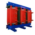
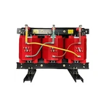
Ambient temperature belongs in the same calculation. A boiler room that idles at 45 °C eats capacity before a single load is energised, so apply the manufacturer's ambient correction rather than assuming nameplate kVA is available. Cast resin dry-type units are usually rated with a 100 K average winding rise on a 40 °C maximum ambient basis, which is why we ask for the temperature of the room, not the outdoor design temperature.
If you are sizing this today, send us the load list and the available fault current and we will run the arithmetic against both. It takes a morning, and it often changes the rating.

Where Standard Ratings Run Out
Catalogue transformers cluster around familiar combinations: 480 V delta primary, 208Y120 secondary, 5.75% impedance, plus or minus two 2.5% taps. Electrification retrofits rarely land on those numbers. A 22 kV / 400 V unit for a Gulf plant, dual secondaries so the boiler bus and the drive bus can be isolated separately, 6% impedance to coordinate with a utility feeder relay, K-13 windings, a wider tap range because the utility voltage sags overnight - the specification stops being catalogue at the second line, which is exactly where industrial electrification retrofits land.
The schedule consequence is worth stating plainly. The U.S. Department of Energy's TRAC programme describes large power transformers as typically custom-made, with delivery lead times of one year or more. The transformer sits on the critical path of an electrification programme, so the electrical design has to start before the boiler purchase order, not after the boiler is installed.
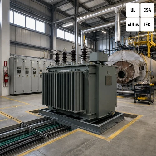
This is the part of the work Ryan Electric was built for. We have manufactured dry-type and oil-immersed transformers since 2007 from a 120,000 m² plant with 180+ sets of production equipment and 37 patents, and since 2023 we have operated as an Eaton joint-venture partner. Units ship with UL, CSA, IEEE, DEKRA, CNAS and CE certification as the destination market requires, with the routine test report the plant engineer will be asked for at acceptance. Most electrification work leaves our shop as a custom three phase transformer rather than a catalogue number, because a load list assembled from a boiler, a heat pump and a drive bus rarely matches one.
A Worked Example From Our Engineering Files
A food and beverage plant in Southeast Asia, client details withheld, came to us with 2,500 kVA already installed at 22 kV / 400 V and three new loads: a 1,600 kW electrode boiler, 450 kW of ammonia heat pump compressors, and 200 kW of new VFD pump load.
Connected load came to 2,346 kVA - 1,600 kVA for the boiler, 511 kVA for the compressors at 0.88 power factor and 235 kVA for the pumps at 0.85. Against the existing 2,500 kVA that is 94% loading, well outside the plant's own 80% rule and outside what the utility would approve without a service upgrade.
We specified a single 3,150 kVA cast resin unit at 22 kV / 400 V, K-13 winding, 6.0% impedance and a +2/-4 x 2.5% tap range, which holds the connected load at 74.5% of nameplate. Two decisions drove that specification. The K-13 winding came from a measured 12% current THD on the existing drive bus. The 6.0% impedance came from the motor-starting study, which held the 450 kW compressor start to an 8.6% voltage dip; 4.5% impedance would have pushed the starting current through the upstream protection settings.
The unit shipped as one custom three phase transformer rather than two standard 1,600 kVA units because the existing plant room offered one foundation pad and no route for a second. That constraint, not the electrical calculation, decided the build.
What We Need Before We Quote a Custom Three Phase Transformer
Ten items. The first three determine whether the quotation is technically valid at all:
- Primary and secondary voltage, and whether the utility service is delta or grounded wye
- Connected kW by load type, with the power factor you actually operate at
- Duty: continuous, cycling or batch
- Harmonic spectrum or K-factor if more than 20% of the load is VFD-fed
- Largest motor rating, starting method, and the voltage-dip limit your specification imposes
- Ambient temperature and altitude of the transformer room
- Available fault current at the service point
- Enclosure type, seismic zone and any corrosive atmosphere
- Tap range, and whether the tap changer must operate on load
- Certification marks and destination country, plus the test reports required at acceptance
Send us the single-line diagram and the load list, and we will come back with a rating, an impedance and a tap range you can defend in a design review. If the boiler nameplate is already on order, say so in the first email - that date decides whether the transformer arrives before the commissioning window or after it.
About the Author
This article was prepared by the application engineering team at Ryan Electric, which has manufactured dry-type, oil-immersed and pad mounted transformers for industrial, utility and data centre projects since 2007. The company operates a 120,000 m² manufacturing base with 180+ sets of production equipment and 37 patents, has been an Eaton joint-venture partner since 2023, and holds UL, CSA, IEEE, DEKRA, CNAS and CE certifications. For a sizing review of an electrification project, send your single-line diagram and load list to the engineering desk at ryan-transformers.com.