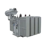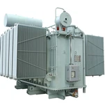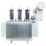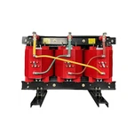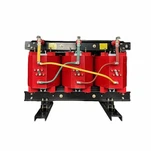


A 20 MW electrolyzer block pulls roughly 22 to 24 MVA out of the grid, and almost all of it passes through two transformer stages before a single stack sees it. Get the second stage wrong and the plant will still make hydrogen. It will simply fail its interconnection study, run hotter than the design intended, and keep failing that study every time the harmonic model is re-run.
Procurement teams usually spend their engineering budget on stack efficiency and balance of plant. The hydrogen electrolyzer transformer is treated as a line item at the back of the electrical package, bought on price and delivery date. That ordering is backwards, because the rectifier interface is where conversion losses, current distortion and DC quality are actually decided.
Where the Hydrogen Electrolyzer Transformer Sits in the Power Chain
A utility-scale electrolyzer plant has a two-stage electrical chain. Stage one is a conventional power transformer that brings 33 kV, 66 kV or 110 kV grid voltage down to a medium-voltage bus somewhere between 6.6 kV and 33 kV. Stage two is the rectifier transformer, which steps that bus down to the AC level the rectifier bridges need and simultaneously provides the phase displacement that cancels converter harmonics.
The load on stage two is not a distribution load. A single alkaline or PEM stack may draw 10 to 20 kA at 1.8 to 2.2 V per cell, and that current has to be held within a few percent across the full load range, because hydrogen output and membrane life both track current density. Converter-duty service is governed by the IEC 61378-1 converter transformer standard, not by IEC 60076, and the difference shows up in how losses, insulation stress and test routines are defined.
The Harmonic Problem: When Six-Pulse Stops Being Enough
A six-pulse bridge produces characteristic harmonics at the 5th, 7th, 11th and 13th orders and beyond. On a grid with a high short-circuit ratio those currents are absorbed without drama. On the weak grids where most renewable-powered hydrogen sites are being built - long rural feeders, islanded industrial parks, networks already carrying a large inverter-based share - they are the reason a project fails its interconnection study. Harmonic mitigation is a transformer specification decision before it ever becomes a filter design decision.
Phase multiplication is the standard answer. Two six-pulse bridges fed from a transformer with a 30-degree displacement between secondary windings form a 12-pulse system, and the 5th and 7th harmonic currents circulate between the bridges instead of entering the grid. Move to a 24-pulse rectifier with four windings displaced at 15-degree intervals and the 5th, 7th, 11th and 13th orders are cancelled as well. The first harmonic current of any size is then the 23rd, where grid impedance is high enough that the resulting voltage distortion stays modest.
| Rectifier configuration | Secondary phase shift | Harmonics cancelled | Where it fits |
|---|---|---|---|
| 6-pulse | none | none - 5th and 7th dominate | Small pilot blocks; requires filters or a stiff grid |
| 12-pulse | 30 degrees | 5th, 7th | Mid-size blocks on reasonably strong grids |
| 24-pulse | 15 degrees | 5th, 7th, 11th, 13th | Utility-scale plants; often meets current limits without filters |
| 24-pulse plus active filter | 15 degrees, closed loop | Residual 23rd and 25th reduced further | Weak grids with a high renewable penetration |
None of that phase multiplication is free. A phase-shifting rectifier transformer carries more windings, more bushings and a larger core-and-tank envelope than a six-pulse equivalent, and the price follows the copper and the floor space. It usually still wins on total installed cost, because the alternative is an active filter or a STATCOM sized for the full harmonic current, and those carry their own losses, cooling demand and maintenance load for the life of the plant.
Specifying the Unit: Loss Factor, DC Ripple and Temperature Rise
Four numbers decide whether a hydrogen electrolyzer transformer survives ten years of near-continuous operation at high load factor.
- Harmonic loss factor. Converter duty raises eddy losses in the windings and stray losses in tank walls and clamping structures. We calculate the loss factor against the actual current spectrum supplied by the rectifier vendor instead of accepting a default K-rating that may not match the load.
- Commutation reactance. Most stack suppliers specify peak-to-peak DC ripple of 5% or better at rated current, and PEM systems often ask for 2 to 3%. Ripple is set mainly by the rectifier topology and the DC smoothing reactor, but transformer leakage inductance feeds directly into the commutation reactance the rectifier designer needs. Give them the leakage figure they ask for, even when it departs from a standard impedance value.
- Temperature rise and cooling. An electrolyzer plant runs at high load factor around the clock. We specify AN/AF or OFAF for converter duty rather than relying on the ONAN nameplate rating, and we confirm temperature rise by heat run rather than by calculation alone.
- Tap range. Grid voltage at a renewable-powered hydrogen site swings with the renewable share on the same connection. A wide tap range on the main step-down unit, commonly plus or minus 8 steps at 1.25%, plus an on-load tap changer on the rectifier transformer, is normal for these projects because the rectifier control range on its own is finite.
Site Conditions Decide the Spec More Than the Stack Does
The IEA's Global Hydrogen Review 2026 puts the announced project pipeline at 27 Mt of annual production by 2030, reduced from earlier assessments, and notes that around 22 Mt of potential output will lose its 2030 window unless investment decisions are taken by early 2027 - two-thirds of it in Europe, North America and Latin America. The consequence for equipment buyers is schedule compression. When a project finally reaches final investment decision, it needs hardware, not another feasibility study.
The same report describes a Middle East region holding roughly one-sixth of global hydrogen production and disrupted by conflict, with urea prices doubling between January and May 2026 and ammonia and methanol trade flows constrained. Diversification of production is now argued as energy security rather than decarbonisation. The US Department of Energy hydrogen programme counts about 10 million metric tons of domestic hydrogen production a year, mostly for refining and ammonia, and names data centers, ports and steel as the emerging demand centres.
Those demand centres translate into transformer specifications that have nothing to do with the stack. Gulf projects run at 50 °C ambient and need the cooling and insulation system sized for it, not for a 40 °C standard rating basis. Ammonia and methanol export terminals sit on coastlines, where a C5-M corrosion system and sealed bushings decide whether the unit is still serviceable in year eight. Projects in Sub-Saharan Africa are frequently connected to grids with low short-circuit strength and poor voltage regulation, which is exactly where the harmonic mitigation strategy above stops being optional.

What We Build Into Every Converter-Duty Unit
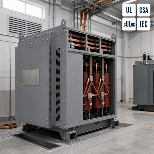
Ryan Electric has been manufacturing transformers since 2007 from a 120,000 square metre plant with more than 180 sets of production and test equipment and 37 registered patents. Since 2023 we have operated as an official joint-venture partner of Eaton, which means converter-duty units are built inside a quality system that a third party audits, rather than a process we police ourselves. We hold UL, CSA, cULus, IEEE, DEKRA and CE certification across our dry type, oil-immersed and pad-mounted ranges.
For rectifier service that shows up in the test bay. Ratio is verified across the full tap range on every unit, impedance and load loss are measured phase by phase, and dry-type units destined for indoor rectifier rooms go through partial discharge testing before they leave. Here is the part most buyers miss: the phase-shift relationship between secondary windings is checked at the winding stage, because a displacement error of a few electrical degrees will not show up in a ratio test but will degrade the harmonic mitigation the whole configuration was chosen for.
An EPC contractor assembling a 30 MW electrolyzer package in the Gulf sent us an electrical specification built around a six-pulse rectifier with a passive filter. We ran the harmonic study against the actual stack current profile and the short-circuit ratio at the connection point, and the projected current distortion at the point of common coupling exceeded the interconnection limit. What we recommended instead was a 24-pulse rectifier arrangement with two phase-displaced secondary sets feeding four bridges, which removed most of the filter duty the utility had been asked to accept. The unit took longer to build than the six-pulse alternative would have. It was still the cheaper route to a signed interconnection agreement.
Lead Times and What Belongs in Your RFQ
Lead times for large power transformers remain extended in 2026, and converter-duty units sit at the longer end because the winding configurations are less standard and the harmonic data has to be exchanged with the rectifier vendor before design can freeze. Anything that removes a design iteration removes schedule risk, so the RFQ should carry the electrical detail up front.
- Rectifier topology and pulse number, with the harmonic current spectrum rather than a single THD target
- Required leakage inductance or commutation reactance per bridge, supplied by the rectifier vendor
- Tap range plus the measured voltage variation profile from the grid study
- Ambient temperature, altitude, seismic class and corrosion category for the actual site
- Certification scope - UL and CSA for North American projects, IEC or CE for export packages - and whether it covers the converter-duty unit or only the main step-down transformer
- Test schedule, including which tests you want witnessed and against which standard
If you are specifying a hydrogen electrolyzer transformer for a project in North America, the Gulf, Southeast Asia or Africa, send our engineering team the rectifier vendor's interface sheet and the grid study. We will come back with a configuration, an impedance figure and a build schedule, and we will tell you where the specification as written is going to cost you money.
About the Author: Written by the engineering and application team at Ryan Electric (Jiangsu Ryan Electric Co., Ltd.), a transformer manufacturer founded in 2007 and an Eaton joint-venture partner since 2023. The company builds UL, CSA, cULus and IEC certified dry type, oil-immersed and pad-mounted transformers for converter-duty, industrial, utility and renewable projects across North America, the Middle East, Southeast Asia and Africa.