

Last March a mechanical contractor in Ontario sent us a one-line for a 12-storey residential tower and one question: can we keep the existing 225 kVA dry type transformer for the new 100 hp electric fire pump? The arithmetic looked comfortable - 225 kVA against a 124 A motor. The unit failed the check that actually governs fire pump design, and it failed by less than two percentage points.
That check is not thermal. A fire pump transformer is sized by the voltage the motor sees in the first two seconds of a start, not by the kilovolt-amperes the building draws at two in the afternoon. Most one-lines that cross our desk have this backwards, and the mistake is expensive in both directions: units that nuisance-trip during acceptance testing, and units carrying forty thousand dollars of copper nobody needed.
Why a Fire Pump Load Does Not Behave Like a Distribution Load
The load profile of a fire pump is nothing, followed by everything. For fifty-one weeks the motor sits idle. Then it starts across the line at full voltage, holds locked-rotor current for eight to twenty seconds, and settles into rated load for as long as the fire lasts. NFPA 20 requires the pump to deliver 150 percent of rated flow at not less than 65 percent of rated head, and the driver has to carry that without overloading - so the steady-state design load is not the nameplate horsepower either.
No diversity factor applies here. No demand factor applies. The pump is not one of forty loads sharing a transformer; at the instant it starts, it is the load, drawing five to six times running current through a winding with no oil to absorb the heat. An oil-immersed unit carries a thousand litres of fluid as a thermal buffer. A cast resin winding has the thermal mass of its own copper and nothing else, so the hot spot responds in minutes rather than hours.
The conversation therefore starts with starting current, ends with a voltage drop number, and only afterwards asks whether the winding survives the duty cycle.
The Two Voltage Limits in NEC 695.7 - and the One Everyone Misreads
Article 695 of the National Electrical Code sets two voltage limits at two different points in the circuit. During motor starting, voltage at the fire pump controller line terminals may not drop more than 15 percent below the controller's rated voltage. Separately, while the motor runs at 115 percent of its full-load current, voltage at the motor terminals may not drop more than 5 percent below the motor nameplate voltage.
Read those again, because the difference between them is the cable budget. The 15 percent is measured at the controller; the 5 percent is measured at the motor, at 115 percent load. Everything between those two points - feeder, terminations, any splice or tap - has to fit inside the gap. A design that spends the full 15 percent at the transformer secondary has already spent the cable allowance.
The second misreading is more common. Contractors apply the 5 percent as a starting limit, conclude the transformer must be enormous, and specify twice the capacity Article 695 requires. The 5 percent governs conductor sizing and regulation at overload, not the starting dip.
Working the Numbers: A 100 hp Pump on a 225 kVA Unit
The voltage drop at the transformer secondary during a locked-rotor start is close to the percent impedance multiplied by the ratio of starting current to rated secondary current. It is a divider: the transformer's impedance fights the motor's starting impedance, and the transformer's share of supply voltage is what the motor does not get.

A 100 hp, 460 V motor has a full-load current of 124 A per NEC Table 430.250 and draws roughly six times that at locked rotor - about 725 A. A 225 kVA unit with a 480 V secondary is rated 271 A. At 4.5 percent impedance the dip works out to 4.5 × (725 ÷ 271), or 12.1 percent.
Twelve percent passes. That is the trap. Add 150 feet of feeder in three parallel runs of 350 kcmil and you spend another point and a half, which puts the controller at 13.6 percent against a 15 percent limit. Nothing is left for a service sitting at 468 V instead of 480, for a tap one step low, or for a second pump starting while the first is still accelerating. Torque falls with the square of voltage, so a 15 percent dip leaves 72 percent of rated starting torque - and a pump already at the top of its curve is exactly where the start stalls and the breaker holds locked-rotor current for twenty seconds.
A 500 kVA unit at 5.75 percent impedance is rated 601 A on the secondary, and the same 725 A start produces 6.9 percent dip. That leaves the cable allowance untouched and absorbs a low utility service without drama. The price difference between those two transformers is a fraction of what a failed witnessed start costs a schedule.
The Locked-Rotor Trap Behind the Fire Pump Breaker
Article 695 requires the fire pump overcurrent device to carry locked-rotor current indefinitely, and NFPA 20 treats any interruption of that supply as a failure of the system. That breaker exists for short-circuit protection only, and it is deliberately selected so it will not open on a stalled start - because a pump that trips on locked rotor is a pump that is not running when the building is on fire.
The consequence for the transformer is unavoidable. During a stall, 725 A flows through a winding rated 271 A, which is 268 percent of nameplate, and nothing interrupts it. Dry type loading curves allow overload only for limited time, and they assume defined pre-loading and defined ambient. A tower with a jockey pump cycling on pressure and a weekly churn test is not that duty.
So the sizing rule has two halves that the same unit must satisfy. The voltage half decides the minimum kVA that holds the dip inside Article 695. The thermal half decides whether the winding survives repeated locked-rotor events at that kVA. On a 150 °C rise design with a 220 °C insulation system there is margin; on a unit built to the thinnest copper that passes the routine test, there is not much.
Where the Fire Pump Taps In Changes the Whole Sizing
Article 695 wants the fire pump supply dedicated - a separate service, a dedicated on-site source, or a connection ahead of the main service disconnect - with no other loads on that path. Where the utility delivers at 13.8 kV into a customer-owned transformer, none of those options exist at 480 V until someone buys a transformer. That is where the engineer and the owner usually disagree about money.
Two answers work. A dedicated fire pump transformer sized only for the pump and its controller accessories, where both the dip arithmetic and the thermal duty use the pump alone. Or a tap ahead of the building main off the common transformer, which is legal, common, and means the unit carries building demand and locked-rotor current in the same winding at the same moment. Take the second path and the kVA has to cover building demand plus the start, with the dip calculated from a loaded transformer rather than a cold one. We see that arrangement most often on retrofits, where a fire pump is added to a service sized years earlier for a diversified load that never included a 100 hp motor starting across the line.
A Sizing Table and Six Lines for Your Specification
The table applies the approximation to 480 V secondaries with typical impedances for each kVA class. Treat the dip column as a screening number, not a stamped calculation - a real study includes motor starting power factor, cable impedance and the actual tap position.
| Pump motor | FLC (NEC 430.250) | Approx. locked rotor | Transformer | %Z | Calculated dip | Verdict |
|---|---|---|---|---|---|---|
| 50 hp | 65 A | 390 A | 150 kVA | 3.0% | 6.5% | Comfortable |
| 100 hp | 124 A | 725 A | 225 kVA | 4.5% | 12.1% | Passes, no margin |
| 100 hp | 124 A | 725 A | 500 kVA | 5.75% | 6.9% | Recommended |
| 150 hp | 180 A | 1,080 A | 300 kVA | 5.0% | 15.0% | At the limit, reject |
| 150 hp | 180 A | 1,080 A | 750 kVA | 5.75% | 6.9% | Recommended |
Six lines belong on a fire pump transformer specification sheet, and each one has decided a project we have quoted:
- Measured percent impedance at the tap you will actually use, not the nominal-tap figure from the catalogue.
- The 115 percent running check documented at the motor terminals, not inferred from the starting case.
- Starts per hour and churn-test frequency taken from the mechanical specification, because that is the thermal duty.
- Room ambient in July, not the 40 °C default - a 50 °C electrical room costs you usable kVA.
- Fire pump controller type: a variable-speed limited-service controller cuts starting current to roughly 300 percent, which changes the dip calculation and adds harmonics worth a K-rating conversation.
- Enclosure: NEMA 2 indoors in a rated electrical room, NEMA 3R if the unit sits on a pad outside.
How We Build and Test These Units
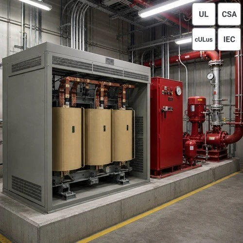
Ryan Electric builds fire pump transformers from 15 kVA to 2,500 kVA, cast resin and VPI, listed to UL 1561 with cULus marking and available against CSA C22.2 No. 47 for Canadian projects. Every unit runs the routine sequence - winding resistance, ratio, polarity and phase relation, no-load loss, load loss, impedance, applied and induced potential - and the impedance printed on the nameplate is measured at the tap the engineer specified, which is the value a dip calculation actually depends on.
The plant runs 120,000 square metres with more than 180 sets of production and test equipment, and since 2023 we have operated as an Eaton joint venture partner. Where a fire pump shares a transformer with building load, we run the locked-rotor thermal check against the real duty cycle rather than a general-purpose loading curve.
Send a one-line and a pump nameplate, plus feeder length and utility service voltage. We come back with a dip calculation, a recommended kVA and the impedance at the tap we would build - usually within two working days, and often with the news that the transformer you already specified is fine.
About the Author: This article was written by the engineering team at Ryan Electric, a UL/CSA-certified dry type and oil-immersed transformer manufacturer in Jiangsu, China, and an Eaton joint venture partner since 2023, serving utility, data centre, industrial and commercial clients across North America, Latin America, Southeast Asia and the Middle East.