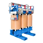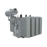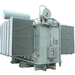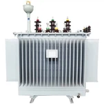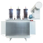


When an EPC contractor in Houston was preparing an electrical equipment skid for export to a mining site in Western Australia last quarter, their lead commissioning engineer called our technical support desk with an urgent question: could they energize a standard North American 480 V, 60 Hz custom three phase transformer directly on a 50 Hz local grid without causing severe core overheating? That practical dilemma is one of the most frequent operational challenges in global industrial electrification. Modular data centers, mobile substations, and industrial skid packages routinely cross regional frequency boundaries between 50 Hz regions (Europe, Australia, Asia, South America) and 60 Hz networks (North America, Saudi Arabia, Philippines).
Operating a transformer at a frequency different from its nameplate design is governed by fundamental electromagnetic physics. While running a 50 Hz unit on a 60 Hz system is generally safe and often beneficial, energizing a 60 Hz unit on a 50 Hz system without proper voltage derating can drive the magnetic core into deep saturation within cycles, triggering extreme excitation currents, excessive core losses, and rapid thermal breakdown. Below is a comprehensive engineering guide on the volts-per-hertz relationship, core flux density shifts, loss recalculations, impedance changes, and factory testing protocols for a custom three phase transformer operating across 50 Hz and 60 Hz power systems.

The Core Electromagnetic Principle: The Volts-per-Hertz (V/f) Relationship
The operating magnetic flux density within any electrical transformer core is defined directly by Faraday's law of electromagnetic induction: E = 4.44 * f * N * Ac * Bmax, where E is the induced root-mean-square (RMS) voltage, f is the operating system frequency, N is the number of winding turns, Ac is the effective magnetic cross-sectional core area, and Bmax is the peak magnetic flux density in Tesla. Rearranging this relationship demonstrates that the peak core flux density is strictly proportional to the volts-per-hertz ratio: Bmax ∝ V / f.
In modern transformer design compliant with IEEE C57.12.00 and IEC 60076-1, a reputable UL listed transformer supplier utilizes high-grade Grain-Oriented Electrical Steel (GOES) engineered to operate near the knee of the magnetic B-H magnetization curve, typically at peak flux densities between 1.60 Tesla and 1.72 Tesla under rated voltage and frequency. Because the core steel approaches saturation around 1.80 to 1.85 Tesla, even small percentage increases in the V/f ratio cause disproportionate spikes in exciting current and acoustic noise level.
Operating a 50 Hz Transformer on a 60 Hz Grid: Two Operational Modes
When transferring a 50 Hz unit to a 60 Hz system, the increased frequency causes the operating flux density to decrease if voltage remains constant. Field engineers can utilize this operating shift in one of two distinct engineering modes:
Mode 1: Constant Voltage Operation (V60 = V50). If the transformer operates at its original nameplate voltage on a 60 Hz supply (for instance, 400 V at 60 Hz on a 400 V / 50 Hz design), the operating flux density drops by 16.7% (B60 = 50/60 * B50 = 0.833 * B50). Operating at roughly 1.35 to 1.43 Tesla places the magnetic core far below its saturation threshold. Magnetizing exciting current drops significantly, core losses decrease slightly, and acoustic sound levels drop by 2 to 4 dB(A). The transformer can safely deliver 100% of its rated nameplate kVA without thermal distress.
Mode 2: Proportional Voltage Scaling (V60 = 1.20 * V50). Because Bmax is proportional to V/f, if the applied primary and secondary voltages are increased by 20% (for example, applying 480 V at 60 Hz to a 400 V / 50 Hz winding), the V/f ratio and core flux density remain identical to the original 50 Hz design baseline. Because the winding conductors can carry their original rated RMS ampacity, the apparent power capacity of the unit scales up by 20% (kVA60 = 1.20 * kVA50). However, this mode requires verifying that the winding insulation class, dielectric clearances, and tap changer voltage withstand ratings can accommodate the elevated operating potential.
Operating a 60 Hz Transformer on a 50 Hz Grid: Mandatory Voltage Derating
The reverse transition-applying a 50 Hz supply to a 60 Hz designed unit-is far more hazardous. If rated 60 Hz voltage is applied at 50 Hz without adjustment, the V/f ratio increases by 20% (60/50 = 1.20). A core designed for 1.65 Tesla attempts to reach 1.98 Tesla, driving the electrical steel deep into magnetic saturation.
Under saturation, the core steel cannot absorb the magnetic field, forcing magnetic flux to spill into surrounding structural clamping frames, tank walls, and winding insulation. The magnetizing current spikes from a normal 1% to 2% of rated full-load current up to 20% to 50% or higher, producing severe localized eddy current heating, rapid thermal breakdown of paper or resin insulation, and nuisance tripping of upstream protection relays.
To prevent catastrophic saturation, a 60 Hz transformer operated on a 50 Hz system MUST have its primary operating voltage derated to no more than 83.3% (50/60) of its rated 60 Hz value. Consequently, its deliverable power rating must also be derated to 83.3% of nameplate kVA to maintain rated conductor current density. A standard 1500 kVA, 480 V, 60 Hz unit becomes a 1250 kVA, 400 V unit on a 50 Hz utility feed.
Engineering Comparison: 50 Hz vs 60 Hz Operational Shifts
The electrical and thermal impacts of frequency conversion across all operating scenarios are summarized in the engineering comparison table below:
| Operating Scenario | Core Flux Density (Bmax) | Total Losses & Thermal Impact | Percent Impedance (%Z) |
|---|---|---|---|
| 50 Hz Unit on 60 Hz (Rated V) | Decreases by 16.7% (B60 = 0.833 B50) | Core loss decreases; load loss slightly higher; cooler core | Increases by ~20% (higher inductive reactance XL) |
| 50 Hz Unit on 60 Hz (+20% V) | Unchanged (constant V/f ratio) | kVA capacity increases 20%; total heat rises proportionally | Increases by ~20% (higher voltage drop at rated current) |
| 60 Hz Unit on 50 Hz (Rated V) | Increases by 20% (DEEP SATURATION) | Massive excitation spike, extreme overheating, risk of fire | Decreases by ~16.7% (distorted waveform, saturation) |
| 60 Hz Unit on 50 Hz (Derated V ≤ 83.3%) | Unchanged (safe V/f ≤ 1.0) | Core loss stable; kVA derated to 83.3%; normal thermal rise | Decreases by ~16.7% (higher secondary fault current) |
Loss Breakdown, Reactance Shifts, and Custom Three Phase Transformer Cooling Limits
Beyond core flux density, frequency transitions alter internal loss components and system impedance characteristics governed by US Department of Energy efficiency guidelines:
Core Loss Components: Total core no-load loss consists of hysteresis loss (Ph ∝ f * Bmax^1.6) and eddy current loss (Pe ∝ f^2 * Bmax^2). At constant voltage on 60 Hz, the drop in Bmax compensates for higher frequency, resulting in total core losses that are slightly lower or equal to 50 Hz operation. When a 60 Hz unit is derated in voltage at 50 Hz, core losses drop slightly, preserving high operational efficiency.
Load Losses and Skin Effect: Load losses comprise DC winding I^2R loss and AC stray eddy losses in conductors and structural tanks (Pstray ∝ f^2). At 60 Hz, eddy current losses in heavy secondary busbars and windings increase by 4% to 10%, slightly elevating load losses at full rated current. For high-current low-voltage secondary windings in a dry type transformer for data center or industrial rectifier applications, winding transposition must be verified to prevent local hot spots.
Impedance and Short-Circuit Level: Transformer leakage reactance is directly proportional to frequency (XL = 2 * pi * f * L). Transitioning from 50 Hz to 60 Hz increases percent impedance (%Z) by approximately 20% (for example, from 5.00% to 6.00%). This results in slightly higher voltage drop under low-power-factor loads but beneficially reduces downstream prospective short-circuit fault current. Conversely, a 60 Hz unit operated at 50 Hz sees a 16.7% reduction in %Z, which increases secondary fault currents and requires checking the interrupting ratings of downstream switchgear and circuit breakers.
Cooling Pumps and Forced-Air Fans: Auxiliary cooling fan motors and oil pumps designed for 50 Hz induction operation will run 20% faster on a 60 Hz supply (3600 RPM vs 3000 RPM), increasing cooling airflow and oil circulation. However, fan motor current draw and acoustic noise will rise. Conversely, 60 Hz auxiliary motors running on 50 Hz will slow down by 16.7%, reducing heat dissipation capacity and demanding additional thermal derating on forced-cooled (ONAF/OFAF/AF) units.
Engineering Dual-Frequency Solutions at Ryan Electric
When global projects demand equipment that can be redeployed across regional boundaries, specifying a dual-rated nameplate (50/60 Hz) on a custom three phase transformer eliminates field guesswork and compliance risks. At Ryan Electric, our 120,000 square meter manufacturing base in China houses over 180 advanced production and automated testing systems, supported by 37 technical patents. Through our Eaton official joint venture partnership established in 2023, we combine world-class electromagnetic design with precision manufacturing that seamlessly bridges North American ANSI/IEEE standards and international IEC frameworks.
As an established UL listed transformer supplier and premier pad mounted transformer manufacturer, every dual-frequency unit engineered by Ryan Electric is designed around the 50 Hz base magnetic core geometry. Sizing the core cross-section and turn ratios for the 50 Hz baseline ensures the unit operates at 60 Hz with exceptional energy efficiency and zero saturation risk. Whether deploying a dry type transformer for data center architectures or heavy-duty pad-mounted substations, every unit undergoes rigorous factory acceptance testing in our ISO 17025 accredited test bay-including full excitation loss curves, induced overvoltage withstand, and temperature rise validation-with dual-rated 50/60 Hz data certified on the stainless steel nameplate before export.
Whether you are specifying dual-frequency pad-mounted substations for international infrastructure, sizing VPI dry-type units for multi-regional data center skids, or evaluating voltage derating factors for exported industrial machinery, our application engineering team is ready to assist. Contact Ryan Electric today to order your custom three phase transformer or receive technical submittal drawings, loss evaluation spreadsheets, and factory lead-time schedules tailored to your project.
About the Author: The Ryan Electric Engineering Team specializes in the electromagnetic design, thermal optimization, and manufacturing of UL/cUL listed, CSA certified, and IEC compliant liquid-immersed and dry-type transformers for mission-critical data centers, renewable energy collectors, and global industrial infrastructure.