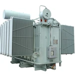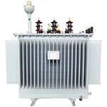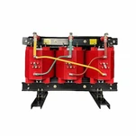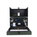


A plant engineer in Texas sent us a photograph in July: a top-oil gauge sitting at 92 °C at four in the afternoon, with the load log showing 18% above nameplate. His question was blunt - how long can we keep doing this? Transformer overload capacity has a real answer, and it is not a percentage printed on a spec sheet. It is a temperature, and the IEEE C57.91 loading guide that defines it has not changed its physics since 1995.

What "Overload" Actually Means on a Nameplate
A transformer with a 65 °C-rise insulation system - the modern North American default - is designed to hold an 80 °C hot-spot rise at rated load. Add the conventional 30 °C ambient and the winding reaches 110 °C at nameplate. That figure is not arbitrary: it is exactly the hot spot temperature at which IEEE C57.91 sets its aging reference, the point where the aging acceleration factor equals 1.0 and the unit is expected to deliver its full design life of 180,000 hours - about 20.5 years. The 55 °C-rise units still in service across older networks sit on a lower reference and tolerate far less.
Two temperatures decide what happens next, and they are not the same measurement. You can review the formal definitions in IEEE Std C57.91-2011 before you go further.
| Quantity | What it measures | Where you read it | Design basis |
|---|---|---|---|
| Top-oil temperature | Bulk oil temperature at the top of the tank | Dial gauge or RTD in the tank cover | Rated top-oil rise above ambient |
| Winding hot spot | Hottest point inside the winding | Calculated, or a winding temperature indicator / fibre-optic sensor | 80 °C rise at rated load (65 °C-rise units) |
This is the part most buyers miss: the gauge on the tank reads oil, and oil is not where the insulation dies. During a load ramp the winding runs ahead of the oil by 10 to 20 minutes, so a unit that looks comfortable on the dial can already be hotter than the dial suggests.
The Two Equations Behind Transformer Overload Capacity
C57.91 does not publish one maximum percentage, and any supplier who quotes one is skipping the physics. It publishes a thermal model. Two equations carry the whole calculation.
Top-oil rise at any load: ΔθTO = ΔθTO,R × ((K²R + 1) / (R + 1))^n - where K is per-unit load, R is the ratio of load loss to no-load loss, and n is roughly 0.8 for ONAN and ONAF cooling, 1.0 for forced-oil modes.
Hot-spot gradient over top oil: ΔθH = H × ΔθWR × K^(2m), with m between 0.8 and 1.0 and H the hotspot factor - around 1.1 for distribution units, up to 1.3 for large power transformers when design data is unavailable.
Total winding hot spot: θH = θA + ΔθTO + ΔθH, with θA the ambient temperature.
Run those numbers on a real unit. Take a 2,500 kVA ONAN distribution transformer with a loss ratio R of 6, a rated top-oil rise of 55 °C and a rated hot-spot gradient of 25 °C - typical heat-run values for this class. Load it to K = 1.25 at 30 °C ambient:
ΔθTO = 55 × ((1.25² × 6 + 1) / (6 + 1))^0.8 = 75 °C
ΔθH = 25 × 1.25^1.6 = 36 °C
θH = 30 + 75 + 36 = 141 °C
At 141 °C the aging acceleration factor lands at about 19. The insulation consumes its design life roughly nineteen times faster than at the 110 °C reference - about 0.25% of life per day, or 22% across a 90-day summer peak. That is the trade a 25% overload actually offers: a quarter of a load step of extra throughput, paid for with a fifth of a 20.5-year service life.

The Four Loading Categories - and Which One You Are In
C57.91 sorts every loading decision into four named categories, and each one carries its own ceiling. The limiting quantity is a temperature, never a kVA figure.
| Loading category | When it applies | What it costs |
|---|---|---|
| Normal life expectancy loading | Day-to-day operation at or near nameplate | Design life preserved; aging near the reference rate |
| Planned loading beyond nameplate | Predictable peaks, a few hours per day, planned in advance | Aging above normal, tracked and accepted as an asset management decision |
| Long-time emergency loading | One unit out of service for days and the load cannot be moved | Heavy insulation aging; every event logged |
| Short-time emergency loading | Hours during a genuine system event | Highest permissible temperatures; exceptional use only |
The guide's own framing is worth restating in plain language: loading above nameplate involves risk, and the document exists to identify that risk and set limits that keep it acceptable. It is not a licence for free capacity, and it does not promise a service life.
Where Overload Plans Fall Apart in the Field
The calculation needs four numbers from the factory: R, the rated top-oil rise, the rated hot-spot gradient and H. Most quotations never include them, which pushes the engineer onto the standard's default values. Those defaults are conservative by design, so they understate what the unit can really carry - and buyers end up paying for capacity they already own.
Ambient is the second trap. The 30 °C basis is generous in the places our customers actually install. At 45 °C - a normal Gulf Coast, Middle East or Southeast Asian summer afternoon - the same load pushes the hot spot temperature 15 °C higher. Ambient correction belongs on the first page of the study, before anyone considers ordering a larger transformer.
Cooling is the third. A fan that is offline, a partly blocked radiator bank, a low oil level, a dust-loaded cooling duct: each one erodes the rise basis the arithmetic assumes. Our service engineers apply one rule - prove the cooling is available before you bank on the overload.
The most expensive overload failures we hear about are not caused by load. They are caused by a cooling system nobody inspected in three years.
Cooling Upgrades and Documentation Change the Math First
Moving a unit from ONAN to ONAF with factory-fitted fans raises the rating basis and changes the exponent in the top-oil equation, which widens the permissible cyclic loading window without touching the core and coils. It only works when the transformer was specified with that provision. Adding fans to a sealed distribution unit after delivery is rarely practical, and never cheap.
Documentation is the other lever. Ask for the heat-run test report with measured rises, the loss data and a load-capability curve. With lead times of a year or more now normal on new orders, more owners are running thermal studies on units already in service instead of waiting for replacements. The installed fleet will not turn over quickly either, because compliance with the amended U.S. distribution transformer efficiency standards is not required until on or after April 23, 2029 according to the U.S. Department of Energy.
Ryan Electric builds oil-immersed and cast-resin dry-type units for utility, industrial and data center duty as an Eaton joint venture partner, with UL, CSA, IEEE and DEKRA certification in the portfolio. The heat-run data used in the example above ships with the test report as standard, not after three emails - because a cyclic loading plan is only as good as the rises it is built on.
What to Ask Before You Plan an Overload Window
Add four items to the RFQ before you commit to any loading strategy:
Measured rises, not guaranteed values. The heat-run report should show the actual top-oil rise and hot-spot gradient of the unit offered, not the design limit.
Load-capability curve at your site ambient. A curve built on 30 °C is not a curve for a 45 °C site, and the gap is where surprises live.
Cooling provision specified at order. Fans, pumps or a spare radiator bank only help if the unit was built to accept them.
Loss data for the study. R drives the top-oil calculation, and an approximate R makes the whole answer approximate.
If your project is pushing existing units harder while new ones are still a year out, send us the nameplate and the heat-run data through ryan-transformers.com and our engineers will run the numbers against your actual duty cycle and ambient profile. We would rather tell you the honest ceiling of your transformer overload capacity than sell you a transformer you do not need yet.
About the Author: This article was written by the engineering team at Ryan Electric, a transformer manufacturer in Jiangsu, China and an Eaton joint venture partner, producing oil-immersed, dry-type and pad-mounted transformers for utility, industrial and data center projects across North America, Southeast Asia, the Middle East and Africa. Factory testing follows IEEE and IEC procedures, with UL, CSA and DEKRA certification available for North American and international projects.