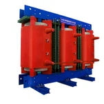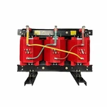


A 1,000 kVA dry-type unit is bolted to its pad, the feeders are landed, and a commissioning crew is an hour away from energizing a new production line in Ontario. Then the megohmmeter settles at 180 MΩ after 60 seconds - and barely moves for the next ten. The polarization index comes out at 1.15, the contractor raises a flag, and the schedule stops while everyone argues about whether the transformer is wet, contaminated, or simply cold. On a unit that left our test floor with a clean report, that argument is solvable in half a day.
Here is the part most buyers miss. A transformer insulation resistance test is not a pass-or-fail stamp. It is an absorption measurement, and the useful information sits in how the reading moves with time and with winding temperature, not in the raw number on its own. Run the tests in the right order, read the trends, and you can separate surface contamination from moisture from a genuinely damaged winding before anyone closes a breaker.

What the Insulation Resistance Test Actually Measures
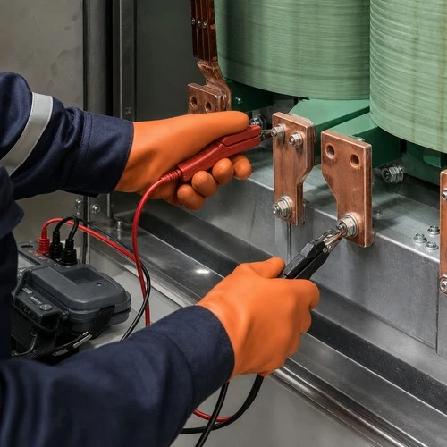
A megohmmeter applies a DC voltage between a winding and ground - or between two windings - and measures the current that leaks through the insulation system. On a cast resin dry type transformer, that system is epoxy, air, and creepage distance. On an oil immersed transformer, it is Kraft paper, pressboard, and the oil itself. Same test procedure, two very different physical systems, which is why the interpretation bands are not interchangeable.
Three currents flow during the test. Capacitive charging current collapses within seconds. Absorption current, the slow polarization of insulation molecules, decays over minutes. Leakage current is the near-steady residue that reflects the actual condition of the insulation. A 60-second reading is still dominated by absorption; the 10-minute reading is much closer to leakage alone. That difference is the diagnostic, and it is the reason a single number tells you so little.
Test voltage follows the winding class. Field crews diverge here more than anywhere else. Our guidance, consistent with the published test codes, is roughly 500 V DC for a 600 V class winding, 1,000 to 2,500 V DC for 2.4 kV to 15 kV class windings, and 5,000 V DC above that. Too low and the reading floats on instrument noise; too high and you stress the very insulation you are trying to assess. The detailed procedures are set out in IEEE Std C57.12.90-2021 for liquid-immersed distribution and power transformers and in IEEE Std C57.12.91-2020 for dry-type units.
Polarization Index: The Number That Separates Moisture From a Cold Morning
The polarization index (PI) is the ratio of the 10-minute insulation resistance to the 1-minute reading. The dielectric absorption ratio (DAR) does the same job with the 60-second and 30-second readings - faster, less accurate, and useful when a unit cannot be held offline for ten minutes.
The classic acceptance bands come from decades of oil-paper practice: a polarization index above 2.0 is healthy, 1.5 to 2.0 warrants investigation, and below 1.5 - especially approaching 1.0 - points to moisture or conductive contamination. Two cautions apply before anyone condemns a transformer. First, a brand-new cast resin dry type transformer often reads a PI below 1.5 simply because cured epoxy contains very little absorptive material; the meaningful comparison is against the factory test sheet for that serial number, taken at a recorded temperature. Second, readings taken on a cold, humid morning in a partially built switchgear room are often dominated by surface leakage across dusty bushings or terminal blocks. Cleaning, drying and guarding the surface can shift the number further than any repair ever will.
Record temperature, never estimate it. Insulation resistance roughly halves for every 10 °C rise in winding temperature. A 180 MΩ reading at 10 °C and a 400 MΩ reading at 25 °C can describe the same unit in the same condition. Any specification that quotes a minimum value without a temperature reference is incomplete, and any comparison between two readings taken at different temperatures is meaningless until it is corrected.
Turns Ratio and Winding Resistance: Catching What IR Cannot See
Insulation resistance says nothing about a broken strand, a loose internal connection, or a winding that took a mechanical hit in transit. Two low-voltage tests cover that ground, and both belong in the same afternoon as the insulation resistance test.
The turns ratio test (TTR) excites each winding and compares the measured ratio against the nameplate ratio on every tap position. A deviation beyond roughly 0.5% is a finding, not a rounding error: the tap changer may be off position, a lead may be landed on the wrong terminal, or turns may be shorted. Winding resistance measurement then balances the phases, with phase-to-phase deviation normally expected inside about 2% once every reading is corrected to a common temperature. Resistance is the test that exposes a connection which will overheat under load, and it is the one field crews skip most often because it takes time and patience.
The accepted field scope for all of these checks is written down in ANSI/NETA ATS-2025, the acceptance testing specifications used across North America to define which tests must be performed before initial energization and in what sequence. The document sets out what to test and what values are acceptable; how to test belongs to the manufacturer's published data and the IEEE test codes.
Test Sequence Changes the Result
Sequence is not a formality. Winding resistance and turns ratio are low-voltage DC tests that leave the insulation system charged to some degree, and any insulation resistance test must be followed by a full discharge. Discharge for at least four times the test duration. Skip it and you create two problems: a shock hazard for the next person on the unit, and a falsely depressed reading when the test is repeated.
Record ambient temperature, humidity and winding temperature before the first test is run, and keep the sequence below as the working order for the day.
| Step | Instrument / input | What it catches | Practical note |
| Visual and mechanical | Inspection only | Transit damage, blocked ventilation, shipping braces left in place, loose terminations | Photograph everything before the first energization |
| Winding resistance | Micro-ohmmeter, DC current | Loose or broken internal connections, tap changer contact problems, strand damage | Correct each phase to one common temperature before comparing |
| Turns ratio, every tap | TTR set, low voltage AC | Wrong tap position, shorted turns, leads landed on the wrong terminal | Deviation beyond roughly 0.5% from nameplate needs an explanation |
| Insulation resistance | Megohmmeter, 500 V to 5,000 V DC by winding class | Moisture, contamination, gross insulation defects | Take the 15 s, 60 s and 10 min readings with winding temperature recorded |
| Polarization index | Calculated from the same test | Moisture and ageing in oil-paper insulation | PI above 2.0 for oil-paper; compare dry-type units with the factory sheet |
| Discharge | Test set | Stored charge in the insulation system | Discharge for at least four times the test duration |
What We Do in the Factory Before a Unit Ships
Every unit that leaves our test floor goes through the sequence above, and the report is tied to the serial number stamped on the nameplate. We record the winding temperature at the moment of each reading, because that single line is what turns a site measurement into a comparable number. Last year a contractor called from a site in Alberta with a 60-second reading at roughly half the factory value. The winding temperature explained it: the unit had been sitting at −8 °C overnight, and once the reading was corrected, it matched the factory sheet within a few percent. The transformer never had a problem. The comparison did.
That discipline rests on scale and third-party verification: a 120,000 m² manufacturing base, more than 180 sets of production and test equipment, and 37 patents, with units qualified to UL, CSA, IEEE, DEKRA and CNAS requirements. Since 2023, Ryan Electric has operated as an official joint venture partner of Eaton, and the test documentation that ships with our transformers follows the same acceptance logic our own engineers apply in the field.
If you want to see what that documentation looks like before you buy, ask any supplier for a sample factory test report with the winding temperature column intact. The format tells you more about how a factory works than any brochure. Request a sample factory test report from our engineering team.
Three Situations That Look Like a Failure, and Are Not
A low reading on a cold, humid morning. Surface leakage across dirty bushings or terminal blocks, not wet insulation. Clean and dry the surface, use the guard terminal or a guard band, record the winding temperature, and retest.
A depressed reading after ocean freight. A breathing unit that crossed an ocean can carry moisture into the paper and oil. The answer is a dry-out or oil processing cycle, not a rewind - which is why we specify the shipping preservation method by destination climate rather than by habit.
A low polarization index on a new dry-type unit. Cured cast resin has almost no absorptive material, so a modest PI is normal. Judge the unit against its own factory sheet, not against an oil-paper threshold.
The reverse case deserves the same attention. On an oil-paper unit, a high insulation resistance paired with a poor polarization index is a worse signal than a moderate reading with a strong ratio, because the ratio is what indicates moisture in the paper - the part of the insulation system that cannot be replaced.
What to Keep With the Asset
Commissioning data stays useful for thirty years, but only if it carries the conditions of the test: winding temperature, ambient temperature, humidity, applied DC voltage, the 15-second, 60-second and 10-minute readings, the calculated polarization index, the ratio at every tap, and the resistance of each phase. Filed against the serial number, that sheet becomes the baseline for every future reading - and the difference between a maintenance decision and a guess.
Send us a site reading with the winding temperature and we will compare it against the factory record for that serial number. One email settles a question that a shutdown meeting cannot resolve. Talk to our engineering team about your project's commissioning scope.
About the Author
This article was prepared by the engineering team at Ryan Electric (Rui'an Electric), a transformer manufacturer founded in 2007 with a 120,000 m² production base, more than 180 sets of manufacturing and test equipment, and 37 patents. Ryan Electric builds cast resin and VPI dry-type transformers, oil-immersed units from 10 kV to 200 MVA, and UL/CSA certified pad-mounted transformers for data center, utility, industrial and renewable energy projects across North America, Southeast Asia, the Middle East and Africa, and has operated as an official joint venture partner of Eaton since 2023. Field test procedures referenced in this article follow IEEE test codes and ANSI/NETA acceptance practice.