


Sizing and Specifying Transformers for EV Charging Stations: A Technical Guide
A single 350 kW ultra-fast charger pulls more current in 15 minutes than a typical convenience store uses in three hours. That load profile - sudden, intense, repeated dozens of times a day - is what makes specifying a transformer for EV charging station infrastructure fundamentally different from standard commercial power distribution. Get the sizing wrong, and the consequences cascade fast: voltage sag that throttles charging speed, demand charges that crush the operator's margin, and worst case, a utility rejection letter that delays the project by months.
The global public charging network is expanding at a pace utilities haven't seen since the air conditioning boom of the 1950s. The International Energy Agency projects the global public charger count surpassing 15 million units by 2030. Behind every charging hub - whether a six-stall Level 2 setup in a shopping mall garage or a 40-stall ultra-fast plaza on an interstate corridor - sits a transformer that has to handle a load pattern no distribution textbook from the 1990s ever accounted for. This guide walks through how to size, specify, and get utility-approved for the right transformer, using real scenarios from projects we've supported at Ryan Electric.
What Makes EV Charging Loads Different from Standard Commercial Loads
A commercial office building transformer sees a fairly predictable day: HVAC ramps up at 7 AM, lighting holds steady, equipment loads fluctuate within a ±15% band. An [object Object] scenario is closer to an arc furnace - intermittent, high-magnitude current pulses that test every weak point in the distribution chain.
Three characteristics define the difference, and skipping any one of them in the specification will come back to bite you at commissioning.
Intermittent peak with a low average load factor. A six-stall DC fast charging station might carry a connected load of 720 kVA (6 × 120 kW), but the actual utilization factor rarely exceeds 0.4–0.6 in the early years of operation. Here's the part most specifiers miss: when four drivers plug in simultaneously during the evening rush, the transformer sees a near-instantaneous 480 kVA demand spike. Standard distribution transformers are not designed for this duty cycle - the thermal time constant of the windings becomes the limiting factor, not the continuous nameplate rating. The winding hot-spot temperature can climb 15–20°C above what the steady-state calculation predicts, and that's where insulation aging accelerates.
Harmonic current injection. Level 3 DC chargers are essentially large switch-mode power supplies with active front-end rectifiers. Even well-designed units inject harmonic currents in the 5th, 7th, 11th, and 13th order bands. Without proper derating, a transformer operating at a comfortable 80% of its nameplate kVA can run at thermal overload simply because harmonic losses in the core and windings add 10–15% extra heating that the standard temperature rise test never measures. IEEE 519-2022 sets the compliance threshold - total harmonic distortion (THD) below 5% at the point of common coupling - but the transformer itself needs a K-factor rating or a harmonic-mitigation winding design to survive long-term.
Voltage sensitivity of the chargers themselves. A DC fast charger will derate its output power the moment input voltage sags below 90% of nominal. A transformer for EV charging station infrastructure with insufficient impedance or an undersized tap range ends up causing the very problem it was meant to solve - slower charging sessions and irritated drivers watching the clock. The transformer's impedance voltage, typically 5–6% for distribution-class units, directly shapes the voltage regulation curve under this pulsed loading pattern. Specify too low an impedance and the short-circuit current exceeds gear ratings; specify too high and the voltage drop under load kills charging speed.
How to Size a Transformer for Your EV Charging Station - Three Real Scenarios
This is the step where most project timelines unravel. Not because the charger procurement is hard, but because the transformer capacity calculation lands on the utility engineer's desk and doesn't survive scrutiny. We see three distinct sizing patterns in the field.
Level 2 AC Charging - Parking Garages and Workplace Lots
A Level 2 station runs at 240 V AC, pulling 7.2–19.2 kW per port. For a 20-port installation at a typical corporate campus, the connected load totals 384 kVA. Apply a 0.6 demand factor - NEC 625.41 permits this for multiple EVSE units when load management is in place - and the design load drops to roughly 230 kVA. A 300 kVA dry type transformer with K-4 rating handles this comfortably, with headroom for expansion to 30 ports.
The key metric at this scale is not peak capacity. It's transformer efficiency at partial load, because Level 2 stations spend 80% of their operating hours between 15% and 40% loading. Look for a unit with a flat efficiency curve above 98.5% from 35% load upward - the difference between a 98.2% and 98.8% efficiency curve across 6,000 annual operating hours adds up to real money over a 20-year asset life.
DC Fast Charging - 50–150 kW Stalls
A six-stall station with mixed 120 kW chargers: connected load 720 kVA, demand factor 0.7 (higher than Level 2 because DC fast sessions tend to cluster during travel peaks), design load 504 kVA. A 750 kVA [object Object] with K-13 rating and ONAN cooling provides the thermal headroom for back-to-back 30-minute charging sessions. The K-13 rating is non-negotiable at this power level - standard K-1 units will run 15–20°C hotter than nameplate under the harmonic profile of six active rectifiers, and the utility will flag the temperature rise during witness testing.
Ultra-Fast Charging Hubs - 350 kW and Above
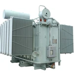
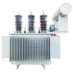
This is the frontier, and the numbers scale fast. Eight stalls at 350 kW each: 2,800 kVA connected. Even at a conservative 0.5 demand factor - realistic for highway corridors with fleet traffic patterns - that lands at 1,400 kVA design load. A single oil immersed transformer rated 2,000–2,500 kVA with forced-air cooling (ONAF) covers present demand and the next 3–5 years of fleet electrification growth.
At this scale, transformer efficiency is the largest single line item in the operating budget beyond electricity cost itself. A 1% efficiency gap across 8,000 annual operating hours at $0.12/kWh costs roughly $13,400 per year. Over a 25-year asset life, that gap buys half a transformer.
|
Charging Scenario |
Connected Load |
Demand Factor |
Design Load |
Recommended Transformer |
K-Factor |
|
20 × Level 2 (19.2 kW) |
384 kVA |
0.6 |
230 kVA |
300 kVA Dry Type |
K-4 |
|
6 × DC Fast (120 kW) |
720 kVA |
0.7 |
504 kVA |
750 kVA Pad Mounted |
K-13 |
|
8 × Ultra-Fast (350 kW) |
2,800 kVA |
0.5 |
1,400 kVA |
2,500 kVA Oil Immersed (ONAF) |
Custom Harmonic Mitigation |
Dry Type vs Oil Immersed: Matching Transformer Type to Site Conditions
The charger count and power level determine the capacity number. The physical installation environment determines which transformer technology actually fits.
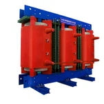
Indoor and underground parking structures. Fire codes in most jurisdictions - NFPA 70 in the US, IEC 60364 in international projects - restrict or outright ban oil-filled equipment in enclosed parking facilities. Cast resin dry type transformers are the default choice here. The epoxy encapsulation self-extinguishes, produces zero oil leak risk, and handles the humidity and dust cycles of parking environments without degradation. Ryan's compact dry type units with IP23 enclosures drop into standard electrical rooms without the clearance setbacks that oil-filled units demand.
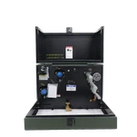
Outdoor charging plazas - retail and highway sites. Here, pad mounted transformers dominate. Oil-immersed, compartmentalized, tamper-resistant, and purpose-built for publicly accessible locations. They handle the larger capacities (500–2,500 kVA) that highway hubs require, and their dead-front design satisfies utility safety requirements in every US state. The pad mount form factor also simplifies the site plan considerably: pour a concrete pad, set the transformer, terminate the secondary feeders to the charger distribution panel. One electrical contractor we've worked with in Texas finishes the transformer-to-first-charger hookup in under four working days with this layout.
Ultra-fast highway corridors. When the site plan calls for eight or more 350 kW stalls, the transformer moves into substation-class territory: 2,500–5,000 kVA, oil-immersed, with on-load tap changers to manage voltage during the wild load swings that occur when a convoy of electric trucks pulls in simultaneously. These units require coordination with the serving utility's planning and engineering teams months before the first shovel hits the ground. No utility approves a 5 MVA interconnection without a full system impact study.
Grid Interconnection: Utility Negotiations That Come Before Everything Else
Hardware selection is half the battle. The other half is getting the local utility to sign the interconnection agreement - and that clock starts ticking earlier than most project developers budget for.
Demand charges define the business model. In North America, a commercial EV charging infrastructure operator pays for peak demand (kW) - the highest 15-minute average draw in the billing month - on top of energy consumed (kWh). Demand charges range from $8–15/kW in markets like California, the Northeast, and Ontario. A poorly sized transformer that forces the site to pull high instantaneous demand spikes during rush-hour clustering incurs demand charges that can consume 30–40% of the station's monthly revenue. The transformer sizing exercise in the previous section is not just an engineering calculation - it is the single largest input into the project's financial model.
IEEE 519 compliance is non-negotiable at the utility review desk. Utilities across North America and Europe now require harmonic studies as part of the interconnection application for any facility exceeding 500 kW of non-linear load. A DC fast charging transformer with harmonic-rated windings and, at larger installations, an active harmonic filter on the secondary side keeps the total demand distortion (TDD) below the 5–8% limits that utilities enforce. File the harmonic study alongside the interconnection request - it accelerates the review timeline by four to six weeks compared to submitting without one.
Power factor correction built into the spec, not bolted on later. Modern DC chargers operate above 0.95 power factor at full load, but that figure drops to 0.85 or lower at partial load - which is where stations spend the majority of their operating hours. A transformer spec that includes integrated power factor correction (or a capacitor bank designed at procurement rather than retrofitted after commissioning) avoids monthly penalty charges and frees up kVA capacity that can serve additional charger stalls without upsizing the transformer.
How Ryan Electric Supports EV Charging Infrastructure Projects
When a charging network developer in California came to us with a site constrained by a 30-foot-wide utility easement and a 12-week construction window, the standard catalog units from domestic manufacturers offered nothing that fit both limitations. We engineered a custom 1,000 kVA pad mounted transformer with a reduced footprint, K-13 rated windings matched to the harmonic profile of their 120 kW chargers, and a fabrication lead time that aligned with their build schedule - not the industry's prevailing 16–20 weeks.
That flexibility comes from running a factory where cores, windings, and enclosures are all fabricated under one roof. For [object Object] projects, our engineering team works from the customer's charger specifications and site layout to produce a transformer datasheet - not a stock catalog page - within three business days of receiving the load list.
What this looks like for an EV infrastructure project:
• UL and CSA listed transformers, accepted by North American utilities without additional field certification
• Compact cast resin dry type units for underground and enclosed parking, where fire codes rule out oil-filled equipment
• K-factor rated pad mounted transformers - K-4 through K-20 - purpose-built for the harmonic environment of DC fast charging
• Standard units ship in 8–10 weeks; custom-engineered units in 10–14 weeks, for projects on compressed timelines
Get a Transformer Spec for Your Charging Station Project
A transformer specification that doesn't account for the harmonic profile, demand factor, and physical site constraints of your specific charging station will land on the utility review desk - and get sent back. The engineering work on the front end costs a few hours of focused calculation. The delay from getting it wrong costs months of schedule slip and the contractor standing by.
Planning an EV charging project in North America, the Middle East, or Southeast Asia? Send us your charger count, power level per unit, and site layout. Our engineering team returns a transformer sizing recommendation and commercial quote within three business days.
→ Contact the Ryan Electric EV Infrastructure Team