


Site Requirements and Installation Checklist for Three-Phase Pad-Mounted Transformers
The installation of a three-phase pad-mounted transformer is a critical phase in electrical infrastructure projects. Precision during the site preparation and placement directly influences the long-term reliability of the unit. As a specialized pad mounted transformer manufacturer, Ryan Electric provides these technical specifications to assist field engineers in meeting regulatory and safety standards.
1. Foundation and Concrete Pad Specifications
The foundation must be constructed to support the full weight of a fluid-filled UL listed transformer, which can range from 3,000 to over 15,000 lbs depending on the kVA rating. Standard engineering practice requires a reinforced concrete pad with a minimum compressive strength of 3,000 PSI at 28 days.
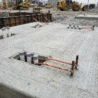
The pad should extend at least 12 inches beyond the enclosure on all sides. A critical detail is the conduit window (cable entry area), which must be sized according to the cable bending radius. It is mandatory that the pad surface has a slight slope (approximately 1/4 inch per foot) away from the enclosure to prevent water accumulation at the base.
2. Grounding Protocols: Ensuring Personnel Safety
Proper grounding is the primary defense against step and touch potential hazards. High-quality grounding requirements dictate a grounding loop consisting of bare copper conductors (typically 2/0 or larger) buried at least 30 inches below grade. All connections between the transformer ground pads and the grounding grid must be made with exothermic welds or high-compression connectors. The resistance to ground should be verified to be less than 5 Ohms prior to energizing.
3. Clearance and Access: Compliance with IEEE Standards
Site layout must adhere to the IEEE C57.12.28 standards for enclosure integrity and accessibility. Standard clearance requirements include a minimum of 10 feet of clear space in front of the cabinet doors to allow for full opening and hot-stick operation. Sideways and rear clearances should be at least 3 feet from combustible walls or vegetation.
4. Lifting and Placement: Preventing Mechanical Stress
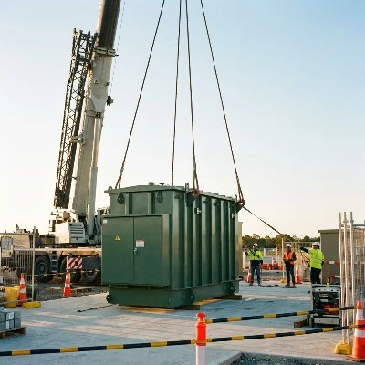
Improper lifting can cause invisible fractures in the tank welds or damage the internal winding support structures. All units must be lifted using the four integrated lifting lugs provided by the pad mounted transformer manufacturer. The lift cables must be of equal length to ensure the unit remains level, with a minimum spreader bar width equivalent to the distance between the lugs to prevent inward crushing forces on the cabinet top.
5. Final Pre-Energization Checklist
Before finalizing the installation, our engineering team requires a thorough check of the following items, as part of our installation safety checklist:
• Verification of fluid levels via the liquid level gauge at 25°C.
• Integrity check of all primary and secondary bushings.
• Torque verification of all cable connections to manufacturer specifications.
• Continuity test of the neutral-to-ground bond.
By following these technical protocols, project managers can ensure that their UL listed transformer performs as designed throughout its 30-year lifecycle. Ryan Electric continues to implement Eaton quality standards across our 120,000㎡ production facility.
About Ryan Electric
Established in 2007, Ryan Electric is an official joint venture partner of Eaton. We specialize in engineering high-performance transformers that meet UL, CSA, and IEEE standards, serving global industries from data centers to renewable energy utilities.