

The tender document that landed on our engineering desk looked clean on first read. 120 MVA, 13.8 kV to 230 kV, ONAN/ONAF, 10 percent impedance – every number a reviewer wants to see. Then we reached the duty line. It said "continuous." Somebody had copied the specification from a thermal plant and changed the project name.
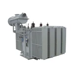
Pumped storage is not a continuous-duty application. It is one of the most punishing duties in a power system, and a hydropower transformer specified for the wrong duty cycle can pass every factory test and still be scrap metal in year twelve. What follows is how we approach hydropower transformer selection for pumped storage, and the five parameters that decide whether a generator step-up transformer is still holding its oil test results at the plant's twentieth anniversary.
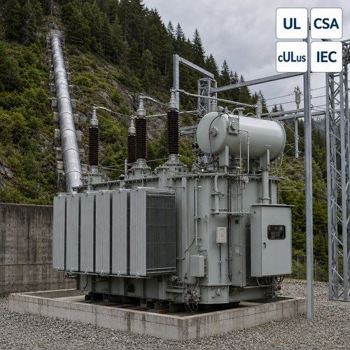
Why Pumped Storage Is a Harder Duty Than Any Baseload Plant
The market signal is hard to miss. The International Hydropower Association's 2026 World Hydropower Outlook reports that global hydropower capacity grew 28 GW in 2025, including a record 11.7 GW of pumped storage hydropower, and that installed pumped storage capacity passed 200 GW worldwide for the first time. Another 243 GW is under construction, and the pumped storage project pipeline now stands at 621 GW. The capacity figures are published on the IHA 2026 World Hydropower Outlook page.
That scale explains why the technology is no longer a niche. IHA's The Paris Pledge puts pumped storage hydropower at more than 90 percent of global electricity storage volume. Utilities are not building these plants to run flat out. Charging happens in the middle of the day when solar output peaks; discharge happens in the evening ramp. A baseload hydro station may see two or three meaningful load changes a week. A pumped storage unit sees two or three a day.
Thermal cycling, not average load, is what consumes insulation life. Every start sweeps winding temperature through a wide band, and the resulting expansion and contraction of conductor, pressboard and clamping structure is a slow mechanical process. Run that twice a day for forty years and you are asking the winding to survive tens of thousands of cycles. That number, not the MVA rating, is what owner-operators of pumped storage plants want to discuss first.
Generate Mode vs Pump Mode: Two Duties in One Tank
In generate mode the machine behaves conventionally. Water falls, the pump-turbine drives the motor-generator, and the generator step-up transformer lifts generator terminal voltage – typically 10 kV to 18 kV on large units – up to transmission level at 220 kV or 500 kV. Nothing in that duty surprises an experienced designer.
Pump mode is where specifications go wrong. The machine becomes a motor, the water is pushed uphill, and the transformer now carries power in the opposite direction, at a different power factor and a different load shape. Two mechanical realities follow from that.
Starting current. A fixed-speed pump-turbine cannot be started across the line. It needs a static frequency converter (SFC), or a back-to-back start from a sister unit, to bring the rotor up to synchronous speed. During that ramp the converter feeds a deliberately distorted, variable-frequency current into the machine – and the transformer sits directly between the converter and the stator, absorbing every harmonic the starting sequence produces.
Reversed power flow. Eddy currents redistribute inside the windings when power direction reverses, and the cooling design has to shed heat from a differently loaded active part. A transformer designed purely around generate-mode loss distribution will run hotter in pump mode than the design calculation suggests.
In our factory we treat pump-mode harmonic duty as a design input rather than a footnote. When a customer sends a specification that names an SFC, we ask for the pulse number, the starting sequence duration and the expected starts per year before we quote impedance.
Five Parameters That Decide Whether the GSU Survives 40 Years
Selection conversations tend to start with MVA and end with price. For pumped storage, five parameters carry most of the long-term risk.
| Parameter | What pumped storage demands | Why it matters |
| Rating and cooling | Sized on the larger of generate and pump ratings; staged ONAN/ONAF/ODAF cooling with each stage documented | Pump-mode power draw can exceed generate output; an undocumented cooling stage cannot be counted in the connection study |
| Impedance (%Z) | Usually specified in the upper part of the 10–14% band typical for large GSUs | Low impedance eases pump-mode acceleration but raises short-circuit duty on a bus that often feeds two machines |
| Tap range and changer type | Off-circuit taps over a wider range; an on-load changer only where daily voltage regulation is required | Pump mode needs voltage headroom to accelerate the rotor; a changer that never moves can fail when it is finally called |
| Temperature rise | 55 K / 65 K top-oil and winding rise per IEC 60076-2, hot-spot checked against IEC 60076-7 | Thermal ageing is cumulative and irreversible; the loading guide converts a 40-year claim into a calculation |
| Transport and assembly | Single-phase units when three-phase shipment weight exceeds the access limit | Equipment that cannot reach the powerhouse has no rating at all – a real constraint on underground stations |
Two of those parameters deserve more than a table row. Impedance sits at the centre of a commercial argument: a lower percentage impedance improves voltage regulation during pump-mode acceleration, but it raises short-circuit current at the station bus, and pumped storage stations frequently have two machines fed from one bus section. The mechanical duty that a fault imposes on the windings is proportional to that current, so the specification has to be resolved against the switchgear rating, not chosen to make one number look better.
Temperature rise is the other. A 55 K / 65 K top-oil and winding rise is described by IEC 60076-2, but the document that turns forty-year life from a claim into arithmetic is the loading guide, IEC 60076-7:2018, which covers loading above nameplate rating, revised thermal models and hot-spot limits. You can inspect the scope on the IEC 60076-7 loading guide page. In pump mode, a fixed-speed unit draws close to rated power for hours; the winding hot spot, not the average oil temperature, is what sets ageing rate.
Harmonics, the Static Frequency Converter, and the Limits of K-Rating
K-rated dry-type units are the standard answer to harmonic loads at distribution level: K-4, K-13 and K-20 are familiar labels in data centre and commercial work. They are not a plug-in answer for a 100 MVA generator step-up transformer connected to a static frequency converter. K-factor assumes a defined harmonic spectrum; an SFC produces a spectrum that changes with rotor speed during every start.
The engineering answer is to evaluate the actual harmonic spectrum and calculate the additional eddy-current loss it produces in the windings, then either specify a harmonic loss factor, derate the unit, or design the winding connection so that triplen harmonics circulate in a delta and never reach the line. On large units we frequently do all three. The 2011 revision of IEC 60076-1 was written partly for this problem: it added a formal definition of harmonic content alongside new requirements for transport and condition monitoring. The scope is listed on the IEC 60076-1 general requirements page.
One practical note from the test bay. Harmonic loss shows up as local heating, so a routine temperature-rise test at 50 Hz will not reveal it. If a specification includes significant converter duty, ask for the loss calculation at the specified harmonic spectrum and for the assumed eddy-current loss factor, and check that both appear in the test report package.
Site Constraints: Caverns, Transport Weight and Cooling Air
Pumped storage plants are usually built where the topography allows two reservoirs close in elevation, which often means an underground powerhouse. That single fact reshapes the transformer specification. An oil-filled unit inside a cavern is a fire-load question before it is an electrical one, and most designs answer it with oil-to-water heat exchangers rather than the radiator banks you would see in an outdoor yard. The heat has to leave the cavern through the cooling water circuit, because cavern air is recirculated.
Weight then decides the architecture. A three-phase oil-immersed transformer in the 150 MVA to 250 MVA class can exceed the load limit of an access tunnel, and a transformer that cannot reach the powerhouse has no rating at all. Splitting the unit into three single-phase transformers is the usual answer – it costs more copper, more floor area and more buswork, but each tank travels within the tunnel limit. IEC 60076-1 devotes a subclause to transport for exactly this reason, and it is worth asking a supplier early whether the design was drawn with the access route in mind.
Humidity and monitoring come next. A cavern unit may be visited monthly rather than daily, so oil temperature, winding temperature and moisture sensors are not optional extras – they are the only way the owner knows the machine is healthy between inspections. Ask for the sensor list and the communication protocol in the quotation, not after commissioning.
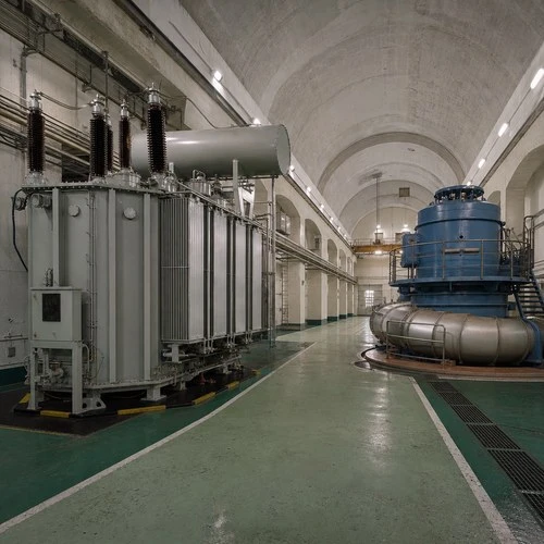
How Ryan Electric Builds and Tests Hydropower Transformers
Ryan Electric has manufactured transformers since 2007 from a 120,000 m² facility with more than 180 sets of production and test equipment and 37 patents in the portfolio. As an Eaton joint venture partner since 2023, we build oil-immersed transformer and dry-type units against UL, CSA, IEEE, DEKRA, CNAS and CE certification requirements, and we serve generation, storage and utility clients across North America, Southeast Asia, the Middle East and Africa.
For pumped storage GSU work, the documentation package is where a supplier is separated from a price list. Our standard submission includes temperature-rise test data measured with fibre-optic hot-spot sensors, impulse and partial-discharge results, short-circuit withstand evidence, the harmonic loss calculation where converter duty applies, and the loading curves that let the owner's engineering team run their own ageing assessment. When the plant is forty years old, those curves are the only proof that the transformer was ever capable of the duty it ran.
What Belongs in the RFQ
If you are specifying a GSU for a pumped storage project, these six lines do more to protect the investment than any brand statement:
Both duty modes stated explicitly, with the number of starts and stops per day and per year for each.
SFC or back-to-back starting method named, with pulse number, start duration and the harmonic spectrum the supplier must design around.
Impedance range bounded on both sides, resolved against switchgear rating and bus configuration rather than a single preferred number.
Temperature rise and hot-spot limits referenced to a loading guide, IEC 60076-7 for mineral-oil units, so ageing can be calculated rather than assumed.
Transport constraints in writing, including access tunnel dimensions, crane capacity and maximum shipment weight.
Test and documentation scope listed, with fibre-optic hot-spot measurement and the harmonic loss calculation confirmed in the contract, not promised in an email.
Pumped storage is being built at a pace the industry has not seen before – 243 GW under construction is a decade of transformer demand. If you are planning a hydro, storage or grid project and want the duty cycle, harmonics and certification handled in one submission, send us your ratings and site conditions through ryan-transformers.com and we will come back with test data, loading curves and a realistic schedule.
About the Author: This article was written by the engineering team at Ryan Electric, an Eaton joint venture partner and UL/CSA-certified transformer manufacturer in Jiangsu, China, supplying power transformers to generation, storage and utility projects across North America, Southeast Asia, the Middle East and Africa.