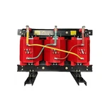


A microgrid transformer spends half its life doing an ordinary distribution job, and the other half doing something no ordinary distribution transformer was ever specified for: holding up an entire facility with the utility breaker open. Most of the specifications that land in our inbox describe only the first half.
When a project engineer sends us a request for a microgrid transformer, the kVA number is usually on page one. The islanded fault current, the neutral grounding arrangement, and the impedance that decides whether the inverters ride through a voltage dip are usually missing. Those three items are what this guide is about.
A Microgrid Transformer Is Not a Small Distribution Transformer
A microgrid is a group of interconnected loads and distributed energy resources that behaves as a single controllable entity toward the grid - and, critically, can disconnect from that grid and keep running. That definition comes from the U.S. Department of Energy's grid research programmes, and it is the origin of every specification difference that follows.
An ordinary distribution transformer has one source on its primary side. A microgrid transformer has to work with two: the utility while the point of common coupling is closed, and the on-site generation plus storage once it opens. That single change ripples through protection coordination, grounding, impedance and loading.
The commercial pressure behind this is no longer a niche story. In a June 2026 analysis, the DOE Office of Electricity reported that total data centre electricity use in the United States climbed from 58 TWh in 2014 to 176 TWh in 2023, and is projected to reach between 325 and 580 TWh by 2028 - with individual sites requesting up to 4.5 GW, roughly the average demand of an entire state. Because distribution and transmission expansion cannot match that pace, the same analysis positions microgrids as the faster route to powering very large loads. Full analysis: DOE Office of Electricity - Microgrids, Large Electric Loads & Grid Support.
Sizing Your Microgrid Transformer for Island Mode
Here is the part most buyers miss. A unit sized from the utility bill is sized for a coincidence of loads that the grid helps to supply. In island mode the same microgrid transformer carries the whole facility through itself, while also absorbing transformer magnetising inrush and the starting current of anything that starts after the transition.
The working method is a load-block study rather than a single demand figure:
- Continuous block - lighting, HVAC and IT or process load that never stops.
- Intermittent block - chillers, compressors and pumps that cycle through the day.
- Motor-starting block - the largest motor, plus any motor that can start at the same moment.
- Charging block - battery storage or EV load the controller may call at any hour.
Then apply a realistic diversity factor and check the worst case: largest motor starting while the transformer already carries its continuous block. A 300 hp motor at six times locked-rotor current draws roughly 2,200 A at 480 V for the first cycles, and that current has to come from somewhere in a system with no utility behind it.
Impedance is where sizing and protection collide. A 1,500 kVA unit at 5.75% impedance on a 480 V secondary delivers about 31 kA of available fault current (1,500 kVA ÷ (√3 × 0.48 kV × 0.0575)). Trim the impedance to 4% to sharpen voltage regulation and the same unit delivers roughly 45 kA - and every breaker, busbar and arc-flash label downstream has to be re-rated to match.
Grounding: The Decision That Sets Your Island Fault Current
When the utility breaker opens, the ground reference the utility provided leaves with it. Unless the microgrid becomes a separately derived system with its own grounded conductor, as required by NEC 250.30, protective devices on the island have no dependable way to tell a ground fault from normal operation.
Three arrangements cover almost every project:
- Solidly grounded wye - simplest and highest fault current; sensible only where the transformer is large relative to the island load.
- Low-resistance grounding - an NGR limits ground-fault current to a defined level, commonly 5 to 400 A, so an insulation fault does not escalate into an arc-flash event.
- Zigzag grounding transformer - creates an artificial neutral on a delta system so the island has a ground reference at all.
The first thing our engineers check on a microgrid specification is not the kVA. It is whether the neutral grounding arrangement matches the fault-detection settings in the inverter or protective relay scheme. A mismatch there produces a system that looks perfect on a drawing and trips on the first real fault.
Harmonics and Ride-Through: Where Inverters Change the Spec
Inverter-based resources do not behave like a synchronous generator. They inject current in discrete switching steps, and a microgrid concentrates that harmonic content because its transformers sit electrically closer to the source than they would in a utility network. IEEE 519 caps voltage total harmonic distortion at 5% on most buses, and a harmonic study - not a rule of thumb - decides whether you need a K-rated microgrid transformer.
Impedance interacts with ride-through as well. IEEE 1547-2018 requires distributed energy resources to ride through defined voltage and frequency disturbances instead of tripping on the first excursion. High transformer impedance deepens voltage sag during motor starts and faults, which can push the point of common coupling outside the ride-through envelope the inverter is configured to hold. Set the impedance with that curve on the table, not after the equipment is ordered. Standards overview: IEEE 1547 series - DER interconnection.
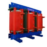
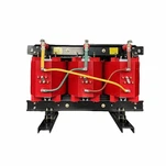
For a dry type transformer for data center and campus applications, two rules we apply on nearly every job: add an electrostatic shield between primary and secondary when sensitive electronics share the bus, and move to a K-13 rating rather than K-1 when the harmonic study shows significant third and fifth harmonic content. Encapsulated cast-resin designs handle both without a liquid fire load indoors.
Certification, Testing and What the Utility Actually Reads
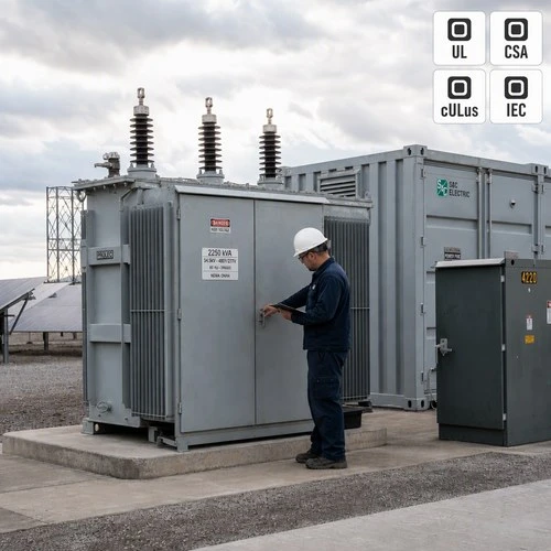
On North American projects the paperwork usually decides the approval. Dry-type units are typically listed to UL 1561, while liquid-filled and pad-mounted units follow UL 1562, with cULus listing and CSA C22.2 compliance for Canadian sites. Efficiency has to satisfy the applicable DOE distribution transformer standard. Then there is the routine test report - ratio, polarity, impedance, winding resistance and dielectric tests, plus a temperature-rise test on the prototype design - which is what a consulting engineer actually reads before signing a submittal.
Working with a UL listed transformer supplier that can produce that file on request saves weeks. Ryan Electric builds dry-type and oil-immersed units in a 120,000 m² facility with 180+ sets of production equipment and 37 patents, holding UL, CSA, IEEE and DEKRA certifications, and has operated as an Eaton joint venture partner since 2023. For a dry type transformer for data center project that means the test report and certification file ship with the unit, not after three follow-up emails.
| Item | Cast-resin dry type | Pad-mounted oil immersed |
| Typical microgrid use | Indoor electrical rooms, data halls, hospitals | Outdoor campus yards, utility-interfaced sites |
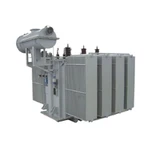
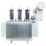
| Fire / siting | No liquid, lower fire load, indoor permitted | Vault or pad separation per NEC 450 |
| Harmonics | K-rated windings and electrostatic shields common | K-rating available; fluid assists cooling |
| Environment | Sensitive to dust and washdown | Suited to rain, snow and coastal air |
| Best when | Indoor, inverter-dense, high harmonic load | Outdoor, distributed, utility-facing connection |

What a Real Specification Walk-Through Looks Like
On a campus project we quoted in Southeast Asia, the buyer's first document was a single-line diagram showing one 2,000 kVA transformer and a 1,600 kW installed load. Nothing in it said what happens when the utility feeder opens. Our reply asked three questions: what is the largest motor, what is the neutral grounding scheme, and what ride-through curve is the inverter set to hold?
The answers changed the order. A single 2,000 kVA unit would have sat at 80% load in island mode, leaving almost no headroom for motor starting - so the design moved to two 1,250 kVA units, impedance fixed at 5.75%, low-resistance grounding at 400 A, and K-13 windings on the section feeding the electronic load. Total kVA went up. Change orders went to zero.
That is the trade a microgrid transformer specification is really making: a slightly larger and more carefully documented unit, against a commissioning week that does not depend on luck.
Specifying Your Microgrid Transformer
Write the island-mode case first and size the transformer second. Send us the single-line diagram, the largest motor, the grounding intent and the certification target. As a UL listed transformer supplier and pad mounted transformer manufacturer with in-house test facilities, we will return an impedance recommendation, a load-block analysis and a schedule that reflects reality rather than hope. Start here: ryan-transformers.com.
The microgrids that hold up under real faults are the ones where impedance, grounding and certification were decided together. That decision is cheapest before the purchase order, and most expensive after commissioning.
About the Author: This article was written by the engineering team at Ryan Electric, a transformer manufacturer in Jiangsu, China and an Eaton joint venture partner since 2023, supplying UL- and CSA-certified dry-type, oil-immersed and pad-mounted transformers to data center, renewable, utility and industrial clients across North America, Southeast Asia, the Middle East and Africa.