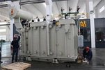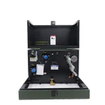


A biomass plant runs on whatever fuel arrives this month - wood chips one week, palm kernel shells the next, refuse-derived fuel after that. The boiler copes with the variation. The electrical system has to cope with it too, and the first place the mismatch shows up is the oil immersed transformer sitting between the generator and the grid. Size that unit from a nameplate load list alone, without allowing for fuel flexibility, motor starting and drive harmonics, and the plant will be re-tapping its auxiliary transformer inside the first year.

Why Biomass and Waste-to-Energy Load Profiles Break Standard Sizing Assumptions
Two plant families get quoted from the same folder and behave nothing alike. A biomass combustion plant in the 10–50 MW class follows fuel availability and heat offtake, so it cycles between roughly 60% and full load month by month. A municipal waste-to-energy plant in the 15–60 MW class runs as must-run baseload, because the city keeps delivering waste whether or not the grid wants the power. Both are grid-connected generation, and neither matches the steady profile that a conventional sizing calculation quietly assumes.
The electrical consequence is not exotic, but it is specific. A biomass power plant transformer that spends its life cycling sees repeated thermal expansion and contraction in the winding and the clamping structure, and it spends long periods at part load where the core is the dominant loss source. IEC 60076-7 gives the ageing guidance for exactly this duty; the practical translation is that a cyclic plant wants a cooling class and a temperature-rise allowance chosen for the load shape, not a nameplate figure copied from a baseload plant. Biomass is not a niche either - the U.S. Energy Information Administration puts biomass at about 5% of total U.S. primary energy consumption in 2025, and the EIA biomass overview (https://www.eia.gov/energyexplained/biomass/) breaks the category down by wood, agricultural residue and municipal waste.
Ambient conditions finish the job. Fuel yards and boiler houses in Southeast Asia and the Middle East routinely sit at 40–45 °C design ambient, with dust from fuel handling and, at waste-to-energy sites, a flue-gas treatment plant drawing heavy auxiliary load. A transformer specified at 40 °C ambient with ONAN cooling and no margin will run its hot spot above the temperature the insulation life calculation assumes. The most common specification error we see on biomass projects is not an under-sized kVA; it is a cooling and impedance combination copied from a solar or wind project where the duty cycle was completely different.
Generator Step-Up Duty: What an Oil Immersed Transformer Must Survive
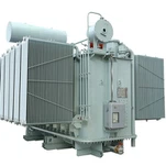
The generator step-up transformer on a biomass or waste-to-energy plant typically takes 11 kV or 13.8 kV at the generator terminals up to 33 kV, 132 kV or 138 kV at the point of interconnection, in the 15–75 MVA range for plants in the 10–50 MW class. Impedance usually lands between 8% and 12%, and the on-load tap changer needs a real range - ±10% in 16 to 20 steps is common - because many biomass sites connect to a remote, weakly supported part of the network where the system voltage moves more than it does at a city substation.
The important difference from an inverter-based plant is what the transformer has to survive electrically. A synchronous generator can push fault current into a fault, so the unit needs a verified short-circuit withstand capability, not an assumed one. Reactive capability and voltage ride-through obligations in the grid code apply through the generator, which means the transformer tap range and impedance have to be co-ordinated with the excitation system rather than chosen in isolation. If the plant must be able to black-start or run islanded during a network outage, the earthing arrangement and the tap strategy have to work with the grid absent - a case that is normally settled on the drawing board, because it cannot be fixed in the field.
The Harmonic Problem: VFD Loads, Air-Cooled Condensers and Flue-Gas Fans
A biomass plant carries a much higher proportion of controlled drive load than a simple gas engine plant of similar output: induced and forced draught fans, feedwater pumps, air-cooled condenser fans, fuel handling conveyors, ash handling, and at waste-to-energy sites the whole flue-gas treatment train. Almost all of it is variable frequency drive load, and drives are harmonic current sources. IEEE 519 caps the current distortion the plant is allowed to inject at the point of common coupling - 5% total demand distortion for most utility interconnections - with a corresponding voltage distortion limit.
Where a six-pulse drive is left unmigrated, current total harmonic distortion at the drive terminals of 25–40% is normal. The usual answers are 12- or 18-pulse drives, an active front end, or line reactors, and each route changes what the transformer has to absorb. A harmonic loss allowance or a K-factor rating changes the winding design, the eddy loss calculation and the temperature rise. That decision has to be made before the transformer order, not after, because a harmonic study that arrives three months late usually means either an oversized filter or a transformer running hotter than its nameplate implies. Our K-rated transformer selection guide walks through the K-4, K-9 and K-13 choices in more detail.
Auxiliary and Station Service Transformers: Where Motor Starting Decides the Rating
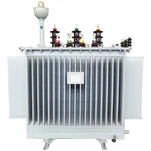
The auxiliary transformer, usually 11 kV or 6.6 kV down to 400 V or 480 V, is the unit that most often gets mis-sized on a biomass project, and the reason is always the same: it is sized on running load instead of starting duty. A 1 MW induced draught fan started direct on line pulls roughly six times its full-load current for the first second or two. The design target is normally a 10–15% voltage dip at the motor terminals, while most utilities cap the dip at the point of common coupling at 3–5%.
There are two ways to get there. Lower the transformer impedance and the dip shrinks, but the available fault current rises, which pushes the LV switchgear rating and the transformer short-circuit withstand requirement up. Or keep the impedance and control the start - soft starter or VFD on the largest motors - which costs less in switchgear and more in drive engineering. Whichever route the plant chooses, the sizing case is the start of the largest motor with every other plant load already running. That case, not the running load list, sets the kVA.
Two practical rules from plant work: size the auxiliary transformer for the motor schedule plus about 20% spare capacity, because biomass plants add conveyors, dust extraction and treatment stages after commissioning; and if the plant has a single auxiliary transformer, treat it as a single point of failure. A second unit or a rated spare is cheaper than a forced outage during harvest season.
Protection, Monitoring and Grid Code Compliance
Protection philosophy on a biomass plant is settled by plant size rather than by convention. Above roughly 10 MVA, the oil immersed transformer at the generator terminals almost always carries differential protection, a Buchholz relay or sudden-pressure device on the tank for internal faults, overcurrent and earth-fault backup, and winding plus top-oil temperature trips. Below that, a smaller unit may be protected by overcurrent and thermal devices alone. The table below is the split we work to on plant projects:
| Duty | Typical rating and voltage | Impedance | Cooling | Tap arrangement | Key protection |
|---|---|---|---|---|---|
| Generator step-up | 15–75 MVA, 11–21 kV / 33–138 kV | 8–12% | ONAN / ONAF | On-load, ±10% in 16–20 steps | Differential, Buchholz, overcurrent |
| Unit auxiliary | 2–6 MVA, 6.6 or 11 kV / 400–480 V | 5–7% | ONAN | Off-circuit, ±2 × 2.5% | Overcurrent, thermal, start blocking |
| Station service / start-up | 1–3 MVA, 11 or 33 kV / 400 V | 5–6% | ONAN | Off-circuit, ±2 × 2.5% | Overcurrent, earth fault |
Two further items belong in the specification. The first is monitoring: biomass and waste-to-energy plants are frequently remote, and a remote plant wants dissolved gas analysis online, fibre-optic winding temperature rather than a simulated hot-spot value, and tap position logging, so that a condition decision does not depend on a site visit. The second is listing. North American biomass projects generally require a UL listed or cULus marked unit, and interconnection authorities now check the certification against the manufacturer database rather than against a document pack - you can run that check yourself in the UL Solutions certification search at https://www.ul.com/. Projects in Southeast Asia, the Middle East and Africa more often follow IEC 60076 with utility-specific addenda, and the addenda is where the real requirements hide.
Specification and Sourcing Checklist for Biomass Projects
Write these six items into the request for quotation and most of the sizing disputes disappear before the bid stage: expected load profile (cyclic duty or must-run baseload); design ambient temperature rather than average temperature; harmonic loss allowance or K-factor if drives dominate the plant; the required impedance band; the tap range and step count the grid code demands; and the short-circuit withstand requirement with the test evidence you will accept.
Loss evaluation deserves its own line. A waste-to-energy plant that runs as must-run baseload will spend most of its life at high load factor, so both no-load and load loss become real money - utilities commonly capitalize no-load loss at a substantially higher rate per kilowatt than load loss when they compare transformer bids. On a biomass power plant transformer that evaluation can be the difference between a standard grain-oriented core and a premium design, and it is far cheaper to run the arithmetic before the order than to explain the energy bill afterwards. WTE generation is a standing part of the U.S. renewable mix; the EIA waste-to-energy overview (https://www.eia.gov/energyexplained/biomass/waste-to-energy.php) summarises how municipal solid waste capacity has moved over the past decade.

Then verify the factory rather than the brochure. For an oil immersed transformer of this size, ask for the routine test protocol against IEC 60076-1 or IEEE C57.12.00, a temperature-rise test on a comparable design (this is the test that proves the cyclic-duty claim), the short-circuit test evidence, and the documentation pack with material certificates for the core steel, winding copper and tank plate. Ryan Electric has built transformers since 2007 in a 120,000 m² facility with more than 180 sets of production and test equipment and 37 patents, working to UL, CSA, IEEE, DEKRA, CNAS and CE requirements, and since 2023 we have operated as an official joint-venture partner of Eaton. For a plant project the useful part of that is simple: we can hand over the test records, and we can run the motor-start and harmonic checks against your motor schedule before the unit is built.
The Next Step
Biomass and waste-to-energy projects rarely fail on the electrical design. They fail on the three inputs that arrive late: the fuel mix, the drive selection, and the motor schedule. Each of them changes the generator step-up transformer or the auxiliary unit, and each of them is cheap to absorb at quotation stage and expensive to absorb after steel is cut.
Send us the single-line diagram, the generator datasheet, the motor schedule and the fuel profile you expect. Our engineers will return a sizing proposal with the impedance and tap range we recommend, a harmonic and motor-start check against your largest drives, and a written confirmation of the test plan before the order is placed. Start the conversation at ryan-transformers.com, or request a quotation and we will come back with the cooling class and loss figures for your duty cycle specifically.
About the Author
This guide was prepared by the application engineering team at Ryan Electric. Our engineers support transformer specifications for power generation, utility, industrial and data centre projects across North America, the Middle East, Southeast Asia and Africa, and have supervised factory acceptance testing for oil immersed units from 500 kVA to 200 MVA. Send drawings, motor schedules and datasheets to our engineering desk for a marked-up review before you issue the purchase order.