

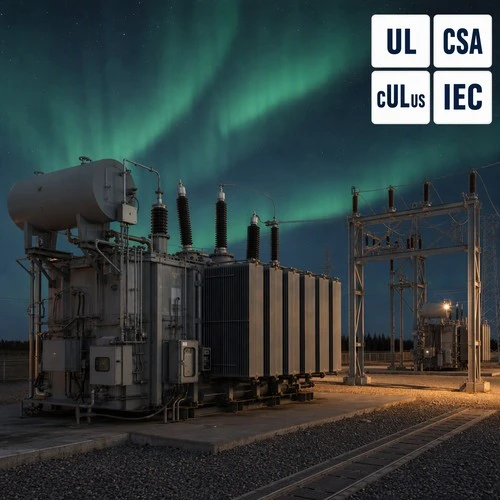
On a clear night in Manitoba, the aurora is not a tourist attraction. It is a signal. When the planetary K index climbs past 5, planners at northern utilities switch from the weather radar to the space weather forecast, because the same solar particles that light up the sky can drive a 60 MVA transformer winding past its design limit within an hour.
The mechanism is not a lightning surge, and it is not a switching transient. It is a slow, quasi-DC current that enters the power system through grounded neutrals and leaves it hundreds of kilometres away. Engineers call it geomagnetically induced currents (GIC), and it behaves nothing like the faults that most transformer specifications are written around.
Why a Solar Storm Arrives as Heat, Not Lightning
A coronal mass ejection throws a cloud of plasma at Earth's magnetosphere. When it lands, the magnetosphere compresses and the ionospheric current systems circulating over the poles intensify. That changing current induces a slowly varying electric field in the ground - a geoelectric field measured in volts per kilometre.
Where that field meets long, earthed transmission conductors, it drives current. Because the energy sits in the millihertz range, the current behaves like DC as far as the power system is concerned. It enters through transformer neutrals, travels along the lines, and exits through neutrals a few hundred kilometres away. Event magnitudes run from tens of amperes to several hundred amperes per neutral, and they last for minutes to hours rather than milliseconds.
NOAA rates these events on a G1-to-G5 scale through its Space Weather Prediction Center. The May 2024 storm reached G5, the extreme category, and settled the argument that the risk is operational rather than theoretical. The agency now runs a dedicated information channel for power system operators, and planners in Canada, the northern United States, Scandinavia and the UK treat it as core input rather than background noise. See the NOAA Space Weather Prediction Center - electric power resources.
What Geomagnetically Induced Currents Actually Do Inside the Winding
Here is the part most buyers miss. Two hundred amps of DC sounds trivial next to a load current measured in thousands of amps. It is not, because of what it does to the magnetic core.
The DC component biases the flux. On one half of every cycle the core saturates - flux can no longer rise in proportion to current - while the other half stays close to normal. The magnetizing current becomes violently asymmetric with a very high peak. Three consequences follow, and none of them is dielectric:
- Harmonic generation. A saturated core produces both odd and even harmonics. Even harmonics are a fingerprint of GIC and are almost absent from healthy operation.
- Reactive power absorption. A saturated transformer stops supplying reactive power and starts consuming it - tens to over a hundred Mvar on a large unit. That is why the grid-level symptom of a GMD event is voltage depression, not visible equipment failure.
- Stray flux and hot-spot heating. Flux that leaves the core path links tank walls, clamps and bolts, inducing eddy currents. The heating concentrates at the winding hot spot and in structural parts that were never designed to carry it.
Hot spot temperature is what decides life. IEEE C57.91, the loading guide for oil immersed transformers, sets the normal hot-spot limit at 110 °C for a 65 °C average winding rise unit, with defined emergency allowances above it. The Montsinger approximation then delivers the bad news: every 6 to 8 °C above the design hot spot roughly halves the mechanical and dielectric life of the cellulose insulation. A GMD event does not have to melt anything to do permanent damage. It only has to hold the hot spot above design for a few hours.
Duration matters as much as magnitude. A two-minute spike is a thermal transient the unit recovers from. A three-hour event is a slow ageing process running in every saturated substation transformer across the affected region at the same time.
Who Has to Prove It: NERC TPL-007 and Thermal Impact Assessments
In North America, GMD resilience stopped being a voluntary engineering exercise years ago. NERC Reliability Standard TPL-007-4, Transmission System Planned Performance for Geomagnetic Disturbance Events, requires transmission planners to test their systems against a defined benchmark GMD event and to evaluate how the transformers on those paths respond thermally to the resulting GIC. Where the study identifies exposure, a corrective action plan follows. The requirements are published in the NERC reliability standards library.
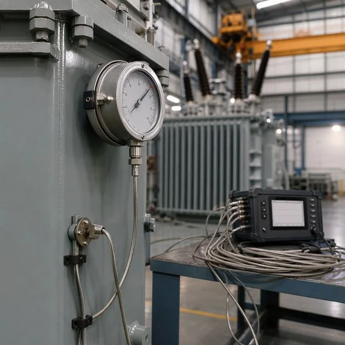
The standard also reaches into the equipment itself. Owners of applicable power transformers have to perform thermal impact assessments, and those assessments need inputs that only a manufacturer can supply: the measured winding hot-spot gradient from the temperature-rise test, the guaranteed loss data, the cooling-stage step points, and the thermal time constants of the specific unit.
That is the practical consequence for anyone buying today. GIC data has moved from the engineering curiosity column into the specification package. If a supplier cannot produce temperature-rise test data with real measured values rather than guaranteed limits, the assessment becomes guesswork - and the planner has to assume the worst case, which is the most expensive assumption in the file.
If you are assembling that documentation now, send your rating, cooling class and site latitude to our engineering desk and ask for the hot-spot data set before the order, not after it. Finding out early whether a supplier actually holds that data costs nothing. Finding out during commissioning costs a season.
What Decides Your Exposure
Not every site carries the same GIC risk, and not every unit on the same site carries it equally. Six factors dominate, and only some of them are inside the buyer's control.
| Factor | What makes exposure worse | What the buyer can influence |
| Geomagnetic latitude | Above roughly 50°, induced geoelectric fields are stronger and GMD events are more frequent | Site location only - effectively fixed |
| Line orientation | Long east–west transmission runs couple more of the geoelectric field | Network planning, rarely single-project level |
| Soil resistivity | Resistive igneous ground forces GIC to find return paths through the network | Nothing at the transformer |
| Winding connection | A grounded-wye neutral gives GIC an entry path; delta windings block it | Winding configuration, written in the RFQ |
| Core and stray-flux design | High-permeability low-loss cores saturate at lower DC bias; unshielded tanks heat faster | Core grade, flux shields, thermal margin |
| Cooling and monitoring | Units without staged cooling or hot-spot monitoring cannot be managed during an event | Cooling class, DGA and hot-spot monitoring |
Note the last two rows. Winding connection and core design are the factors a specification can actually move, and they are the two that most RFQs leave blank. GIC only enters a winding when a grounded-wye neutral gives it a path; delta windings block it. On the magnetic side, high-permeability, low-loss cores saturate at lower DC bias than older core grades, which is worth understanding before anyone assumes that a more efficient transformer is automatically a more GIC-tolerant one.
Specifying for GMD Exposure Without Over-Engineering
Hardening every unit on a system is not the answer, and utilities know it. Two questions decide the conversation: does the site sit in a high-latitude, high-resistivity region, and did the system study flag this unit as a GIC-carrying path? Where both answers are yes, four mitigation routes are available.
| Approach | How it works | Trade-off |
| Neutral blocking device | Inserts DC impedance in the neutral so GIC cannot complete its path through the winding | Adds a component in the protection chain; needs bypass logic and maintenance |
| GIC-tolerant thermal design | Extra thermal margin, flux shielding, low stray-loss construction, staged cooling | Higher material cost per kVA; no dependency on protection |
| Operating measures | Reduce loading ahead of a forecast event and hold reactive reserves | Relies on forecast accuracy and operator discipline |
| Network-side measures | Series compensation or reconfiguration to alter GIC return paths | Transmission-side investment, outside the transformer scope |
Most northern utilities end up with a combination rather than a single fix: a thermally tolerant transformer design as the baseline, operational measures for extreme events, and neutral blocking on the handful of units where the study shows the highest currents. Selecting a substation transformer on the basis of purchase price alone tends to push the cost into the operating phase, where it is far harder to negotiate.
What Our Test Bay Can Give You That a Datasheet Cannot
Ryan Electric has been manufacturing transformers since 2007, from a 120,000 m² facility with more than 180 sets of production and test equipment and 37 patents behind the designs. Since 2023 we have been an Eaton joint venture partner, which means the documentation we hand over - UL, CSA, IEEE, DEKRA and CNAS test evidence - is written for the same reviewers our North American clients face.
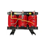
When buyers arrive with a GIC impact assessment template in hand, the fields they need are specific: measured hot-spot gradient at the top cooling stage, the per-stage load addition for each ONAF step, top-oil time constant, guaranteed no-load and load losses at the reference temperature, and the winding connection diagram. On an oil immersed transformer, that data comes from the temperature-rise test and the heat-run record, not from a catalogue table. A dry type transformer faces a related but different thermal question, since GIC exposure in most networks is a transmission-level, grounded-neutral phenomenon.
Our position on GIC is unglamorous but honest: no transformer is immune. What a manufacturer can do is supply data you can defend, margin you can quantify, and a design that keeps the hot spot inside the insulation class when a G4 or G5 event arrives. We would rather quote a unit with a documented hot spot than promise something physics will not deliver.
Preparing for the Next Event
Four actions make the difference between managing a GMD event and discovering it afterwards.
- Baseline your oil data now. Dissolved gas analysis results from during an event are close to unreadable without a pre-event baseline for the same unit.
- Know which units are exposed. Run the GMD screen if you operate under NERC rules. Outside North America the same physics applies at high geomagnetic latitude, whether or not a regulator is asking.
- Use the forecasting window. A G4 or G5 warning gives hours of notice. Reducing loading on the most exposed units and holding reactive reserves is free capacity management.
- Close the documentation gap. If the thermal data for your installed fleet does not exist, that is a procurement problem with a procurement solution: make measured hot-spot data a line item in the next order.
Aurora season is not a marketing event for transformer manufacturers, but it is a useful reminder. The grid we build is designed for faults measured in milliseconds. Space weather tests it with stresses measured in hours, and the units that survive with their insulation life intact are the ones specified with honest thermal data.
Need the Thermal Data Package?
If you are planning a project in a high-latitude market, or answering a GIC data request from your transmission planner, send us the rating, cooling class, winding connection and site details through ryan-transformers.com. We will come back with temperature-rise test data, loading curves and certification files in the format your assessment asks for - not a datasheet that leaves the hard fields empty.
About the Author: This article was written by the engineering team at Ryan Electric, a transformer manufacturer established in 2007 and an Eaton joint venture partner since 2023, producing oil immersed, dry type, pad mounted, rectifier and energy storage transformers under UL, CSA, IEEE, DEKRA and CNAS certification for clients across North America, Southeast Asia, the Middle East and Africa.