

A datasheet landed on our desk last month with 220 kV on the HV winding and IEC 60076-16 in the standards column. Both cannot be right at once. IEC 60076-16 stops at a highest voltage of 72.5 kV, and its scope says plainly that it does not cover the transformer connecting several turbines to the network. What was being quoted was an export unit, three times that voltage and many times the mass.
The gap is not academic. A 220 kV unit designed against the wrong part of the standard inherits the wrong insulation coordination, the wrong test list and the wrong impedance assumptions, and the error usually surfaces at the witnessed FAT, three months before sail-away. Offshore wind is now big enough for these packages to matter: GWEC counted 92.5 GW grid-connected worldwide at the end of 2025, 9.3 GW of it added that year, with the average new turbine at 10.3 MW.
Two Machines, One Wind Farm
The turbine transformer and the export transformer share a factory and almost nothing else. A turbine unit works at 0.69 kV or 1.1 kV on the generator side and 33 kV or 66 kV on the collection side, carries converter harmonics and a load profile that moves with every gust, and fits inside a nacelle weight budget. That is the duty IEC/IEEE 60076-16 was written for.
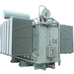
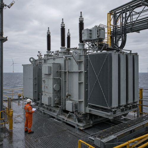
The offshore substation is where a wind farm becomes a power station. Dozens of array feeders arrive at 66 kV, and the offshore wind transformer there steps the aggregate up to 132 kV or 220 kV for the export cable, or higher where distance and losses justify it. Units of 300 MVA to 450 MVA are normal on large arrays, and tank, oil and radiators together can weigh more than the switchgear building beside them.
These are ordinary power transformers in the IEC 60076-1 family, dielectric-tested to 60076-3 and short-circuit-proven to 60076-5. Nothing in that family assumes gust-driven cyclic loading, and nothing in 60076-16 assumes a 220 kV impulse level. The IEC/IEEE 60076-16-2018 scope is explicit about that boundary, which is why getting the family right is the first decision in the specification.
| Parameter | Turbine step-up unit | Offshore substation export unit |
|---|---|---|
| Voltage | 0.69-1.1 kV / 33-66 kV | 66 kV / 132-220 kV |
| Typical rating | 5-15 MVA | 150-450 MVA |
| Governing standard | IEC/IEEE 60076-16 | IEC 60076-1, -3, -5 |
| Duty | Gust-driven cyclic, converter harmonics | Farm aggregate, daily cycling, cable charging |
Weight Is an Electrical Parameter on a Platform
On land, a heavier transformer costs freight. Offshore it costs steel, crane capacity and sometimes the project. Every tonne on a topside is carried by the jacket, lifted by a crane whose load chart is fixed months before the transformer design is frozen, and restrained through a sea voyage that puts stress into the core, bushings and tank in directions no seismic case covers.
We met this on a 132 kV package last year. The fabrication yard chart capped the single lift at 180 t, and our standard 120 MVA arrangement came in about 9 t over once transport bracing was counted. Thinning the tank wall to recover 3 t would have eaten the short-circuit margin, so we moved the radiator bank onto its own skid, re-routed the oil piping and re-ran the transport analysis. The lift closed with 6 t to spare.
Three levers usually decide whether a unit fits: core flux density, radiator placement and oil preservation. Lower flux density adds core mass but cuts no-load loss and sound power, often the right trade where energy yield is the product. Splitting radiators from the tank spreads load but adds oil volume and joints that must be leak-tested as one system.
Sea fastening needs its own calculation, not a note on the general arrangement. The marine warranty surveyor will ask for transport accelerations in g, applied vertically and laterally, and for the resulting stress in tank, core clamps and bushing pads. Bushings above 145 kV class normally travel crated and go in offshore, and an impact recorder read at the quay is the cheapest insurance in the package.
Salt Air: Where Offshore Wind Transformer Corrosion Protection Is Decided
A transformer that spends 30 years 60 km at sea is a corrosion specimen with windings inside. ISO 12944-9 was written for this environment: it covers protective paint systems for steel exposed to corrosivity category CX (offshore) and immersion category Im4, and defines the laboratory tests, including cyclic ageing and salt spray, that a system has to survive before anyone believes the datasheet.
In our paint shop, offshore work changes the process long before it changes the colour. Plate and profiles are blasted to Sa 2 1/2, edges and welds get a stripe coat because paint pulls thin over a sharp corner, and dry film thickness is measured on a fixed grid across every tank, cover and radiator bank. Fasteners are 316L stainless or hot-dip galvanized; electroplated zinc has no place on a platform.
Radiators decide more quotes than tanks do. Cooling fins are thin by function, flex in transit, and a perforated fin is a leak path no coating rescues. We set fin stock thickness and corrosion allowance separately from the tank specification, and leak-test the bank before painting rather than after.
Oil preservation is the other half of transformer corrosion protection. A conservator with a silica gel breather pulls humid, salt-laden air into the tank every time the oil volume moves. A sealed tank with a nitrogen blanket removes that breathing path and takes the breather off a maintenance list that needs a vessel to service.
Cable Charging Changes the Impedance and the Tap Range
An export cable is a capacitor with a conductor inside. A 220 kV XLPE cable carries enough capacitance per kilometre that over 60 km or 80 km the charging current becomes a real fraction of rated current. At light load, a farm producing 15% on a calm night, that current lifts voltage at the offshore end, and the tap range has to absorb it without pushing the onshore substation out of limits.
That is why an export transformer on a large array often lands on an off-circuit tap range of +/-8 x 1.25% rather than the +/-2 x 2.5% copied from a plant template. It is also why the onshore end usually carries a shunt reactor: absorbing charging Mvar is cheaper where there are people to maintain the equipment.
Impedance does two jobs at once. Higher %Z limits LV fault current and protects 66 kV switchgear and array cables; lower %Z holds regulation and cuts reactive consumption. On a unit in the 12-16% range the fault study sets the number and a harmonic impedance scan checks it. Cable capacitance and leakage inductance form a parallel resonance, and if it sits near a converter harmonic, the filter design changes even though the transformer does not.
The Tests Worth Witnessing Before the Unit Sails
A witnessed FAT on an offshore wind transformer of 300 MVA is two days in a test bay and a week of travel. A failure found on the platform is a vessel, a crane and a weather window. The economics are not close, yet the witness list is where buyers try to save money.
Routine and type tests follow IEC 60076-1 and 60076-3: winding resistance, ratio and vector group, no-load and load loss, impedance voltage, insulation resistance, power-frequency withstand, lightning impulse, partial discharge, temperature rise and sound power. Two deserve attention. Partial discharge is judged on trend over the full test duration, not on one pass number. Temperature rise only means something with the cooling stage declared, because ONAN results cannot be sold as ONAF capability.
Beyond electrical tests, ask for the coating record: system, thickness grid, adhesion and a salt spray result from the same batch. Ask for the sea-fastening calculation, the lift plan and weld NDT records on the tank. A pinhole weld offshore becomes an oil sheen, a notification and an insurer question.
What an Oil Immersed Transformer Factory Should Prove
Offshore packages are awarded on evidence, not brochure language. When a buyer audits an oil immersed transformer factory for coastal or offshore work, the test bay says more in an hour than a catalogue does in a week, and the paperwork tells you whether the test bay is telling the truth.
What should be visible: an impulse generator sized for the BIL of the unit, a shielded partial discharge laboratory with background below the acceptance limit, temperature-rise capability at full rating, and a paint line that can hold a CX system with documented thickness. Then the dull evidence: a calibration register, a non-conformance log with closures, and welders qualified to a recognised standard.
Ryan Electric runs 120,000 m2 of manufacturing space with more than 180 sets of production and test equipment and 37 patents, and holds UL, CSA, IEEE, DEKRA and CNAS recognition. Since 2023 we have been an Eaton joint-venture partner. Our 66 kV, 110 kV and 161 kV power transformer lines cover the classes these collection and export systems use, and every unit ships with a test record rather than a summary.
The Procurement Calendar and Four Expensive Mistakes
An export transformer sits on the critical path of every offshore project. Design freeze needs cable data, the fault level study and topside interface drawings, and those three rarely arrive in the same month. A 12 to 18 month order-to-delivery window is realistic for a large unit, and the FAT date should hang off the topside integration schedule rather than the contract signature.
- Quoting a 220 kV export unit against IEC 60076-16.
- Specifying C5-M, a category the 2017 revision of ISO 12944 replaced, instead of CX and Im4.
- Leaving sea fastening and lifting points to the fabricator after the tank design is frozen.
- Buying on price per MVA and ignoring no-load loss.
That last one has a number attached. A 100 kW difference in no-load loss, on a unit seeing 4,200 equivalent full-load hours a year, is 420 MWh a year and about 12.6 GWh over a 30-year life. At 90 USD/MWh that is roughly 1.1 million USD before any carbon price, which is more than the spread between most competing bids.
If an offshore or coastal package is still on the drawing board, send us the single-line diagram, the export voltage and the transport limits. We will return a unit envelope, a loss estimate and a test plan that can go straight to the marine warranty surveyor. Write to Ryancustomerinquiry@redq.cc or use the contact form at ryan-transformers.com.
About the Author: The author is a senior application engineer at Ryan Electric, working on oil-immersed power transformers for utility, renewable and industrial projects. He supports offshore and coastal substation packages through specification review, design freeze and witnessed factory testing, and writes about the details that decide whether a unit commissions cleanly or becomes a claim.