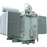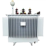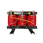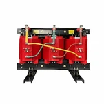


A developer sends us a single-line diagram for 90 MWac of PV and a 60 MW / 240 MWh battery sharing one 230 kV interconnection, and the drawing shows a single 150 MVA unit at the point of interconnection. A month later the EPC sends the same plant with two 100 MVA units instead. Both drawings can be built. Only one of them will still look correct after the first year of dispatch, because a hybrid power plant transformer sits behind two sources that were specified by two different teams with two different duty assumptions.
Four numbers decide which arrangement survives contact with operations: the point-of-interconnection load profile, the impedance between the two low-voltage windings, the zero-sequence path, and the outage strategy. Price, tank size and schedule follow from those four. Here is the order we work through them when a solar-plus-storage single-line lands on our desk.
Why a Hybrid Plant Breaks the Usual Transformer Assumptions
A PV-only plant is easy on a transformer. Output follows irradiance, peaks around midday and falls to zero at night, so the unit gets a long cool-down every day. The IEEE guide for distributed PV transformers notes that an inverter transformer can be loaded for up to 14 hours a day yet sit at 100% for only part of that window, with long no-load periods overnight. Designers lean on that pattern when they accept a nameplate rating with almost no margin.
A battery changes the shape of the day. Charging happens when PV is strong or when night prices are low, and discharge lands in the evening peak. Put both sources behind one interconnection limit and the transformer stops following the sun. It follows a dispatch instruction written by a trader or an optimization algorithm, not by the weather.
Take our example plant. The interconnection is capped at 120 MW. At midday the array produces 90 MWac while the battery charges at 30 MW, so 60 MW crosses the transformer. At 19:00 the array is at zero and the battery discharges 60 MW, so 60 MW crosses the transformer again, in the opposite direction. The unit can sit between 80% and 95% loaded for sixteen hours a day and never see the deep overnight cooldown a PV-only design would receive.
Option A: Two Step-Up Transformers, One Per Source
The conventional arrangement for a solar-plus-storage plant gives each source its own two-winding step-up transformer: a 100 MVA 230/34.5 kV unit at about 8.5% impedance on the PV collector, and a matching 100 MVA unit on the battery collector. Each carries its own high-side breaker, its own differential zone and its own oil system. Nothing electrical couples the two except the 230 kV bus.
The case for this arrangement is failure containment and accounting. A collector fault in the PV field trips one 87T zone and leaves the battery free to discharge into the grid within seconds. Tax equity structures frequently require separate metering per technology, and two transformers make that trivial. Construction also phases cleanly: the PV unit energizes at PV commercial operation, nine to twelve months before the battery enclosure is finished.
The cost is paid in iron and bays. Two cores carry two no-load loss figures around the clock whether or not the plant is generating, plus a second 230 kV breaker, a second set of surge arresters, a second control cabinet and roughly double the concrete. On a site with a spare bay, that penalty is tolerable. At a constrained substation it often is not.

Option B: One Three-Winding Hybrid Power Plant Transformer
The alternative is one three-winding transformer rated 230/34.5/34.5 kV at 150/90/60 MVA, with both collectors landing on separate low-voltage windings. The vector group matters more than most buyers expect. Specify YNyn0d11, not YNyn0. A delta tertiary gives zero-sequence current a path to circulate during a low-voltage ground fault, and it gives third-harmonic flux somewhere to go instead of through the tank steel. Without it, ground fault current on a 34.5 kV collector has no return path through the transformer, and every ground relay setting downstream becomes an estimate.
Impedance is quoted as a pair of numbers, typically 10.5% high-to-PV and 10.5% high-to-battery on the 150 MVA base, which puts the PV-to-battery figure near 19%. That coupling is the hidden cost of the single unit: a fault on the PV collector also pulls the battery bus down, and the battery inverters have to ride through a voltage depression they did not create. Whether they can is a question for the inverter datasheet and the interconnection study, not for the transformer supplier.
What you gain is one high-side bay, one oil preservation system and one core. On a typical 150 MVA three-winding design, no-load loss lands near 90 to 100 kW against roughly 120 to 130 kW for two 100 MVA units at the same total rating. Over twenty years at an eight-cent rate that gap is real money, and it usually wins the bid review. Confirm it against the manufacturer loss calculation, not a datasheet from another project.
What you give up is availability. A bushing failure, a tap changer fault or a failed oil pump takes both revenue streams offline at once, and a 150 MVA three-winding unit is not a stock item. The repair or replacement window is measured in months, not weeks. If the plant has a firm capacity obligation, that exposure belongs in the business case, not in the operations manual after the fact.
The Impedance Number That Cannot Be Fixed Later
Three-winding transformer impedance is set by winding geometry on the core, and once the unit is built there is no adjustment short of a rebuild. If a short-circuit study later concludes that 34.5 kV fault duty exceeds the switchgear rating, the only remedies are a series reactor or a new transformer. On the two-unit scheme the same problem is solved by changing one 100 MVA specification before the purchase order.
Run the study before the specification, not after the award. Ask for the fault current contribution from each inverter family, including the current limiting most modern inverters apply at 1.1 to 1.5 times rated current, and ask what the collector switchgear is rated for. A 150 MVA unit at 10.5% delivers a materially different fault level at 34.5 kV than two 100 MVA units at 8.5%, and the difference can shift you from a 25 kA to a 31.5 kA switchgear class.
Loading, Hot Spot and the Cool-Down That Never Comes
Cyclic loading allowances are the most abused part of a transformer quotation. The IEEE loading guide, revised in 2025 describes how a unit can be loaded above nameplate when a defined peak is followed by a defined cooling period, and it sets out the temperature criteria that govern the trade. Those methods are sound. The problem is that they are usually applied with a PV-only daily curve borrowed from an earlier project.
Feed the guide a hybrid profile instead. A 65 °C rise unit with a 110 °C hot-spot limit, running at 95% load for eighteen hours at 40 °C ambient, will sit close to that limit for most of the day rather than touching it briefly at noon. Insulation ageing roughly doubles for every 6 K above the reference hot-spot temperature, so the difference between a two-hour peak and an eighteen-hour plateau is not a rounding error in loss-of-life terms.
Two practical consequences. First, ask for the 24-hour net interchange curve at the point of interconnection and require the hot-spot calculation at the site design ambient, not at 30 °C. Second, specify the cooling stage honestly: an ONAF rating that depends on fans running continuously is a different asset from an ONAN rating with fans as a boost, and the auxiliary power and fan-failure alarm philosophy should say which one you bought.
Protection, Grounding and Reverse Power
Inverter-based sources do not behave like synchronous machines during a fault. Current is limited, the angle is controlled, and the negative-sequence signature differs from a generator. On a three-winding unit, the differential relay has to handle three restraint currents with ratios that do not match the 90/60 MVA split, and the low-side ground elements must be set against a zero-sequence network that includes the delta tertiary. That is a solvable problem, but it is a relay engineer problem, and it needs to be in scope from the start rather than discovered at commissioning.
Reverse power deserves its own line in the specification. Overnight the battery charges from the grid, so real power flows from the 230 kV winding into the 34.5 kV battery winding through a transformer whose taps were probably chosen for the export direction. The high-side on-load tap changer must cover the actual operating band, typically 0.95 to 1.05 per unit at the interconnection, and a directional element should be set to distinguish scheduled charging from an unintended backfeed. IEEE 1547-2018 governs the inverter side of that interface, including voltage and frequency ride-through, but the transformer impedance and tap range decide whether the plant stays inside those limits in the first place.
Grounding is where the two arrangements diverge most in cost. Two separate units mean two independent 34.5 kV grounding designs, each with its own zigzag unit or grounded-wye with a neutral resistor, each studied on its own. One three-winding unit with a delta tertiary lets both collectors share a zero-sequence reference, which simplifies the study but concentrates the risk: a mistake affects both sources at once.
Choosing Between Them, and What We Ask Before Quoting
| Criterion | Two 100 MVA two-winding units | One 150 MVA three-winding unit |
| High-side bays and breakers | Two | One |
| Total no-load loss (typical) | 120-130 kW | 90-100 kW |
| Outage exposure | One source at a time | Both sources together |
| Differential protection | Two simple 87T zones | One 87T, three restraint sets |
| Zero-sequence path | Independent per collector | Requires delta tertiary |
| Collector fault coupling | None through transformer | PV fault depresses battery bus |
| Delivery and transport | Standard heavy haul | Permits, rail study, longer lead time |
| Best fit | Tax equity metering, phased COD, firm capacity | Single bay, tight plot, loss-driven bid |
Choosing between two step-up transformers and a single hybrid power plant transformer rarely comes down to a technical tie-breaker. Our rule of thumb after a decade of quoting both: if the plant carries a firm capacity obligation or the interconnection has separate metering requirements, take the two units and accept the extra bay. If the substation real estate is fixed, the bay does not exist, and the bid is decided on capitalized loss, the three-winding unit wins and the availability question moves to the spare strategy.
When a developer asks us to quote a hybrid power plant transformer, we ask for five documents before we open a design file: the single-line with the interconnection limit, the 24-hour net interchange curve for a typical spring and summer day, the inverter fault current contribution letter, the grounding study or at least the collector grounding philosophy, and the transport route. The last one is not paperwork. A 150 MVA three-winding unit with oil can exceed 200 tonnes, and the difference between a route that clears a bridge and one that does not is often decided months before steel is cut.
Ryan Electric has manufactured transformers at our 120,000 m2 facility in Jiangsu since 2007, with 37 patents and more than 180 sets of production and test equipment, and we have been a joint-venture partner with Eaton since 2023. That partnership is why the hybrid quotes we issue carry a full impedance and loss study rather than a datasheet copy: the review chain does not accept a rating without the load curve behind it.
If you are weighing the two arrangements for a project in the next twelve months, send the single-line and the dispatch curve. We will return both configurations priced, with the loss and impedance comparison on the same base, so the decision is made on numbers instead of on a drawing someone inherited.
About the Author
This article was prepared by the Application Engineering Team at Ryan Electric (Ryan Transformers), a transformer manufacturer based in Jiangsu, China, supplying dry type, oil immersed, pad mounted and compact substation equipment to North America, the Middle East and Southeast Asia since 2007. The team reviews single-line diagrams, impedance and loss studies and certification documentation (UL, cULus, CSA, IEEE, IEC) for utility-scale solar, storage and data center projects. Ryan Electric has been a joint-venture partner with Eaton since 2023. Specification questions discussed here can be sent through the contact form at ryan-transformers.com. Last reviewed: October 2026.
Disclosure: Ryan Electric manufactures and sells the transformers discussed in this article. Loss, impedance and costing figures are typical design-stage values for the ratings described and must be confirmed against a project-specific loss calculation and short-circuit study before purchase.